
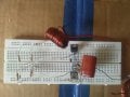
Please guys my rider oscillator circuit isn't working I need you help.
Attachments
-
 169.2 KB Views: 29
| Thread starter | Similar threads | Forum | Replies | Date |
|---|---|---|---|---|
| D | I need a recommendation on a diode please. | General Electronics Chat | 9 | |
| S | Guys please help me out with an equation. | Homework Help | 2 | |
|
|
Can u guys please help ? :) | General Electronics Chat | 4 | |
| A | guys please help with the electronics workbench | Homework Help | 5 | |
| G | Please, can you guys help? | General Electronics Chat | 3 |

by Jake Hertz

by Jake Hertz

by Aaron Carman

by Duane Benson

