Plasma Cutter Repair

Thread Starter

Wasoofa82

Joined Jan 24, 2021
45
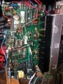
Hello everyone, I am trying to repair a thermadyne pakmaster 25 plasma cutter. When I first started this project the unit was not cutting thru thick metal when I turned up the current knob like it used to. When I took the unit apart I found the power mosfets and two fast recovery diodes had been completely dry of heatsink grease. I did not smell any leaky caps or notice anything burned. I took a gamble and replaced all 8 fets and 1 fast recovery diode, now when I fire the pilot arc on the torch to initiate the cut I just get a sputtering arc and no blasting thru the metal. I was thinking I could of damaged them with ESD. I also replaced one each of npn and pnp transistors near the current adjustment knob with still the same thing.
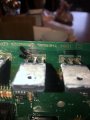
Before I desolder the FETS, I was thinking of doing some poking around with my scope, I dont have any high current or voltage probes. I figured if I poke around the low current and low voltage control side I might find something. I just powered up the unit at idle nothing pressed, I found four test points near a series of driver ic's near the mosfets. The top two red circled points just measure a simple sine wave, the bottom two measure a negative dc offset shifted sine wave.
When I fired the pilot arc while the probing at the top test point I got some kind of modulated waveform with a frequency in the khz range which is what plasma cutters operate at. Here is some pics and the manual that has a schematic. I would greatly appreciate some help
 

Attachments

MaxHeadRoom

Joined Jul 18, 2013
28,576
The Plasma machines I have worked on had HV DC for the arc, are you sure that is not the HF pilot arc frequency you are showing?
Max.

1611505812914.png
 
Last edited:

Thread Starter

Wasoofa82

Joined Jan 24, 2021
45
The Plasma machines I have worked on had HV DC for the arc, are you sure that is not the HF pilot arc frequency you are showing?
Max.
You are right, on the unit there is an led that is lit when there is dc operation in progress, I guess it would be pulsed dc output. Im wondering if I could probe some of the FETS but im scared I might damage my scope. Im gonna order a current probe for my scope and maybe a 100:1 probe. I was thinking using channel 1(drain) and channel2(source), the gate is tied to a driver transformer maybe this is where the high power is located and I should not probe?? Maybe I could somehow see the switching of the fets. I also don't have an isolation transformer, I was probing around without the scope probe earthed.
 

MisterBill2

Joined Jan 23, 2018
18,061
It seems like the device was not working to capacity, but was working before, and now it is not. The first thing would be to verify that all of the connections are adequate, and verify that the devices installed are actually the correct type. Then the question about if the previous devices were insulated from the heat sink or not , and are the replacements installed the same. Since the high power part is what is not functioning iit seems like the 8 mosfets are not getting switched on. Could there be a short circuit in the gate drive area? That would prevent the high power from switching on.
 

Thread Starter

Wasoofa82

Joined Jan 24, 2021
45
I’m kind of a beginner I guess. My degree is a bachelors in electrical engineering technology . I used to work more often with electronics in my previous job where I used to mess with telecommunications test equipment(OTDR’s, tberd bit error test sets). Now in my current job is more quality control and manufacturing of fiber optic cabling and DWDM filters. It’s been about 5 years since I sat down with a circuit board. As far as isolation is concerned, would I need to plug the plasma cutter and my scope into an isolation transformer. I’m could I use a current probe on the cd (capacitive discharge transformer wires).
 

MaxHeadRoom

Joined Jul 18, 2013
28,576
Just the 'scope isolated.
Often on the larger tables, a small current detection device is used on the H.V. lead to detect arc transfer such as Honeywell CSDA10C .
Max.
 

Thread Starter

Wasoofa82

Joined Jan 24, 2021
45
Also I forgot to mention the first time when I removed the mosfets they were in a very difficult to remove conformal coating. It’s was a really thin layer that just chipped off, it had to be like an oil based coating. I had absolutely no choice but to burn it off with my soldering iron outdoors.
I ended up wearing out one solder tip. I did end up ripping up a couple pads for my effort. Initially I was asking around to figure out if these pads were critical and if I could just flow in some extra solder because the board is only a two layer. Previously I re-removed the solder and marked some pictures to help further illustrate the effected areas. Here are the pics that I took with numbers that correspond to the top and bottom side of the board. I then figured it would not be necessary to run some kynar jumpers.
So here I am for the second time I re-assembled the unit and have the same exact problem from the first time around. I hope this is not confusing. The conformal coating did not even smell like Humiseal. It smelled just like the rosin core flux. I absolutely would not burn conformal coating its just down right nasty and breathe the nasty fumes. Humiseal I’ve always just peeled it up
 

Attachments

MisterBill2

Joined Jan 23, 2018
18,061
Since it is a double sided board there were plated through holes and the replacement parts may not be soldered to both sides of the circuit board now. ands undoubtedly that will make a great dealof difference.
 

Thread Starter

Wasoofa82

Joined Jan 24, 2021
45
Hello, I went back and traced the lifted pads the best I could. I made some kynar jumpers which are shown in the picture. Now I’m getting a very weak high frequency pilot arc which is not even blue, more orange in color. I think I might of shorted something with the jumpers. I went back and powered the unit on and off and snipped each wire at a time to see if anything changed. Nothing different!!. I also measured one of the testpoints with my scope before I began snipping, now the sine wave is centered I’m getting no negative dc offset shift, I guess this is called clamping??0B14AD38-C8AB-4CB6-8645-148EF4CF0408.jpeg
 
Top