Facebook
 Google
 GitHub
 Linkedin
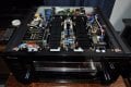
I have an older 2006ish model pioneer Elite receiver (among other similar models) that I am attempting to modify.
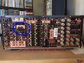
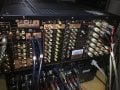
You see some higher end models have a "pre-amp in / out" where you can bi-pass the internal audio processing (bass, treble, loudness, delay, echo, etc) instead it passes the signal directly to the amp chips themselves. And I have some much cleaner sounding pre-amps that work much better than the internal pre-amp in most recivers. So I'd like to solder in some wires from an RCA input on the back directly into the amplifier section, because this series of recivers has a nice compartmented set of boards. So there is a power board then a DSP processing board a volume/input managing board, a pre-amp board and of course the amplifier section.
Most of it is easy to figure out what each ribbon cable between them is carrying (signal/voltage wise) as most of it is printed right on the PCB plus I also have the schematics.
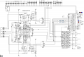
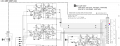
The pre-amp board in this unit even shows the various channels printed as "FL / FR / SR / SL / C" (as in Front Left Surround Right etc...) however in each of these sections on the PCB output connector there are 5 pins/traces per channel labelled as "GATE+ / GATE- / BIAS+ / BIAS- / NFB" I am not sure which one carries the pre-amplified audio signal? I mean there are no other wires going into the amplifier section (other than from the power board). So the audio must be carried along 2 of these 5 pins!
I assume "GATE" is for turning the amp channel or or off - thus I assume that "BIAS" would be the "gain/volume bias audio"?
But I am not sure, thus I am here asking if anyone might have so input as to how a typical Pioneer reciver lables things.
I have provided a portion of the schematic here with some RED/BLUE dots where I assume the pre-amplified audio signal is?
You see some higher end models have a "pre-amp in / out" where you can bi-pass the internal audio processing (bass, treble, loudness, delay, echo, etc) instead it passes the signal directly to the amp chips themselves. And I have some much cleaner sounding pre-amps that work much better than the internal pre-amp in most recivers. So I'd like to solder in some wires from an RCA input on the back directly into the amplifier section, because this series of recivers has a nice compartmented set of boards. So there is a power board then a DSP processing board a volume/input managing board, a pre-amp board and of course the amplifier section.
Most of it is easy to figure out what each ribbon cable between them is carrying (signal/voltage wise) as most of it is printed right on the PCB plus I also have the schematics.
The pre-amp board in this unit even shows the various channels printed as "FL / FR / SR / SL / C" (as in Front Left Surround Right etc...) however in each of these sections on the PCB output connector there are 5 pins/traces per channel labelled as "GATE+ / GATE- / BIAS+ / BIAS- / NFB" I am not sure which one carries the pre-amplified audio signal? I mean there are no other wires going into the amplifier section (other than from the power board). So the audio must be carried along 2 of these 5 pins!
I assume "GATE" is for turning the amp channel or or off - thus I assume that "BIAS" would be the "gain/volume bias audio"?
But I am not sure, thus I am here asking if anyone might have so input as to how a typical Pioneer reciver lables things.
I have provided a portion of the schematic here with some RED/BLUE dots where I assume the pre-amplified audio signal is?
Attachments
-
 364.3 KB Views: 15