piezo buzzer with a sorry-ass data sheet

Thread Starter

mikewax

Joined Apr 11, 2016
184
Are you using a high current magnetic buzzer that needs Mosfets to drive its high current, or are you using a low current piezo transducer that uses such a low current that a Cmos Logic IC can drive it? A Cmos logic IC has six inverters in it that can drive it bridged.
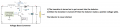
well here's the circuit and the 20mm disks and the 120mH inductor. i'm lookin to get as much volume as humanly possible within the extremely limited space i have. the inductor is exactly 6mm thick. and so is the housing it's gonna fit in, so i'm gonna use a booster and the hbridge driver to bump the voltage up to about 20V or more. i calculated IAVG at about 110mA at 2800Hz. i don't know about the kind of chip your talking about. if it means fewer parts, that would be great. :)
edit: that's wrong Iavg is about 55mA.

buzzerCircuit.png
 
Last edited:

Thread Starter

mikewax

Joined Apr 11, 2016
184
What is the supply voltage?
Is there a specification for the required current at twice the supply voltage?
How is the required square wave to be produced?
What is going to be used to enable sounding (i.e. turn it on and off)?
If the sounder is a small piezo disk type it can be readily driven with twenty five cents worth of common CMOS.
man i sure wish it were that easy. see my illustration in #29 above. i been workin for days to solve some REALLY tough design criteria.
to be precise, i'm gonna use a booster to get 10V, then use the Hbridge to create a 20V square wave (much obliged, that was an awesome idea), or more if i can.
hmmm... just realized i miscalculated. the IAVG will be about 50-60mA, which is about as much as the choke can handle. i'll raise the voltage until i reach the choke's current capacity. but it's kinda iffy since the buzzer will only be operating for a couple seconds at a time so i don't really know how much it can handle.
anyway i'm using an ATTINY24 for the drive signal. and i turn it off by dropping the SHDN line on the voltage booster that feeds the bridge.
 
Last edited:

JohnInTX

Joined Jun 26, 2012
4,787
Late to the party but FWIW, the gizmo in #29 is a little auto transformer that steps up the drive voltage to the piezo to a couple hundred volts for a big one. A sample circuit is shown here (last circuit diagram).
https://www.challengeelectronics.co...11-Piezoelectric-Transducers-Applications.pdf

I coded the driver in a project some time ago but I don’t recall where we got them. IIRC it took about a 33% duty cycle pulse at the resonant frequency of the transducer.
 

Thread Starter

mikewax

Joined Apr 11, 2016
184
Late to the party but FWIW, the gizmo in #29 is a little auto transformer that steps up the drive voltage to the piezo to a couple hundred volts for a big one. A sample circuit is shown here (last circuit diagram).
https://www.challengeelectronics.co...11-Piezoelectric-Transducers-Applications.pdf
I coded the driver in a project some time ago but I don’t recall where we got them. IIRC it took about a 33% duty cycle pulse at the resonant frequency of the transducer.
by all means the more the merrier. i sure wish i had found that page a few days ago.
my real problem is that an autotransformer is not an option. GOD KNOWS who makes them or where i can get one, and even if i did, it's too big for the housing. my current plan is kida like the #3 circuit on page two of your document. but if i can get more volume with the #5 circuit i'll do that. who know what the resonant f of the disks is.
 
Last edited:

Audioguru

Joined Dec 20, 2007
11,248
if i can get more volume with the #5 circuit i'll do that. who know what the resonant f of the disks is.
Who says a piezo disc needs a current as high as 110mA?
Every piezo transducer sold by Digikey (395 of them) has a detailed datasheet showin the resonant frequency and the low level frequencies near it. But how will you tune the inductor?
Your H-bridge uses huge high current Mosfets that are made to drive a high power motor not a low current little piezo.
Those Mosfets need a gate voltage of 10V to fully turn on and off but the TINY24 cannot provide it. Then the P-channel Mosfets will never turn off and the N-channel Mosfets will never turn on.
 

takao21203

Joined Apr 28, 2012
3,702
120 mH (mllihenry) ?? I doubt it.
110mA ? Also questionable.

These autotransformers are used for some chinese gadgets, but havent seen them on the market.
But I could get them in quantity, 50, 100, 1000. what ever.
Single piece, its not worth the efforts.

Id say the piezo disc doesnt use constant current. Its a capacitor of a kind so when it has no charge its pretty much a short.
TO the information I have it could be some 30 to 40nF, mainly depending on disc size.
 

Thread Starter

mikewax

Joined Apr 11, 2016
184
Who says a piezo disc needs a current as high as 110mA?
Every piezo transducer sold by Digikey (395 of them) has a detailed datasheet showin the resonant frequency and the low level frequencies near it. But how will you tune the inductor?
Your H-bridge uses huge high current Mosfets that are made to drive a high power motor not a low current little piezo.
Those Mosfets need a gate voltage of 10V to fully turn on and off
please pardon the inacurate illustration. what i meant to illustrate (see my description above) is like this. and yes, i'll get one at digikey. ebay parts don't include any info. also, that was a math mistake. the current is more like 50mA wholeCircuit2.png
from the datasheet: " the LV8458 is a low saturation voltage forward/reverse motor driver IC" IOmax = 1A
spec.pngi haven't figured out yet how to tune the circuit. i'll look online for some kind of frequency claculator.
 
Last edited:

Thread Starter

mikewax

Joined Apr 11, 2016
184
120 mH (mllihenry) ?? I doubt it.
believe me, so did i when i found it. i couldn't believe a part that small could have that much inductance. but it was just the miracle i needed to make this #!*$ work. (http://www.cooperindustries.com/con...duct-datasheets/Bus_Elx_DS_4315_DR_Series.pdf, look at the bottom of page 4)
110mA ? Also questionable.
yeah that was a mistake. it should've said 50mA
These autotransformers are used for some chinese gadgets, but havent seen them on the market.
But I could get them in quantity, 50, 100, 1000. what ever.
Single piece, its not worth the efforts.
well i did finally find a few of them an aliexpress, but they don't have any data and they're still too big.
Id say the piezo disc doesnt use constant current. Its a capacitor of a kind so when it has no charge its pretty much a short. TO the information I have it could be some 30 to 40nF, mainly depending on disc size.
thanx for the estimate. i'll refigure the math. the one's i'm gonna use will be about d = 20mm.
 
Last edited:

takao21203

Joined Apr 28, 2012
3,702
You could measure the disc, simply.

Im going to try if I can get some of these transformers and to find out maybe theres different sizes.
It will take some while though.
 

Audioguru

Joined Dec 20, 2007
11,248
The Mosfets in the LV8548 will short the inductor and eliminate its voltage peaking. Then the inductor is useless.
You must tune the TINY's frequency to match the mechanical resonance of the piezo for the highest sound level.
 

Thread Starter

mikewax

Joined Apr 11, 2016
184
You could measure the disc, simply.
Im going to try if I can get some of these transformers and to find out maybe theres different sizes.
It will take some while though.
WOW if you could find one that would work i'd have a second lease on life! i thought the only way to get one would be to wind my own. because it would have to have an OD = 6mm. but then there'd be no way to get more of them.
the disks i have are 21mm to be exact. i'm gonna look for others on digikey.
THANX i really appreciate that. i'll keep my fingers crossed. :)
 

Thread Starter

mikewax

Joined Apr 11, 2016
184
The Mosfets in the LV8548 will short the inductor and eliminate its voltage peaking. Then the inductor is useless.
i don't get your meaning. i thought it's supposed to short the choke, like a switch mode booster. isn't that the whole point?
You must tune the TINY's frequency to match the mechanical resonance of the piezo for the highest sound level.
well i'm gonna find one of those online calculators to do that.
 
Last edited:

Thread Starter

mikewax

Joined Apr 11, 2016
184
Last edited:

AlbertHall

Joined Jun 4, 2014
12,345
You could also use one of the chips intended for driving RS232 line levels from an mcu like the MAX232.
There is an example circuit here intended for driving 40kHz piezo transducers.
 

Audioguru

Joined Dec 20, 2007
11,248
The frequency of your LC will be -10% to +10% if the parts have a 5% tolerance on their values. The mechanical resonant frequency of the piezo also has a + or - tolerance. They must be tuned to be the same or the output level will be too low.
A piezo beeper has a feedback terminal on the piezo that feeds the oscillator so it always beeps at the frequency that produces the highest output level. Your circuit has no feedback.
A switch mode booster puts a lot of current into the inductor then the voltage increases when the current is stopped. The inductor is never shorted. Your H-bridge shorts the inductor.
 

Attachments

Thread Starter

mikewax

Joined Apr 11, 2016
184
A piezo beeper has a feedback terminal on the piezo that feeds the oscillator so it always beeps at the frequency that produces the highest output level. Your circuit has no feedback.
A switch mode booster puts a lot of current into the inductor then the voltage increases when the current is stopped. The inductor is never shorted. Your H-bridge shorts the inductor.
sorry, i said it wrong. as i understand it, the circuit sends an inductive spike into the disk the same way a booster circuit does and that's how you get a high volume, like in this circuit:
basic.png
i was also assuming that the only easy way to double the voltage is by driving the Hbridge with a differential signal from the uC. and i could choose the frequency and the inductor to match the disc frequency. as i understand it, i can use this disc (https://www.digikey.com/product-detail/en/pui-audio-inc/AB2025B/668-1004-ND/1464743, C = 80nF, f = 2k5) with a 50mH (way less than the choke i was intending to use) choke and according to this calculator (http://www.daycounter.com/Calculators/LC-Resonance-Calculator.phtml) it would match almost exactly the fR of the disc.
 
Last edited:
Top