Need Piezo Buzzer in circuit for 10 sec alarm

Thread Starter

NewHobby1

Joined Jan 9, 2025
4
Hi,

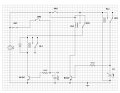
New to this forum , need suggestions to add Piezo Buzzer which sound only when SW2 open till discharge of C1.

SW1, SW2, SW3 are connected with pressure system , play open /closed as per system condition.

Situation 1 = When SW1 closed and SW2 closed then RL1 is ON and
Situation 2 = When SW3 closed RL1 is still ON with RL2 and RL3 .
Situation 3 = When SW3 Open RL1 remain OFF for next 30 Sec due to RL2
Situation 4 = When SW2 Open and SW1 and SW3 are closed then RL1 remain ON only for 10 Sec .

Solution required for A Piezo Buzzer alarm for same 10 sec when only situation 4 happens? How to achieve it ? already Tried many scenarios .

All 4 Situation working in this circuit but Buzzer not work as desired . any suggestions? any improvement in this circuit?

I have little knowledge how electronic circuits works .
 

Attachments

sghioto

Joined Dec 31, 2017
8,633
The TS mentioned only in Situation 4 would the buzzer sound. :rolleyes:

Using the RL1 relay contacts the buzzer will sound anytime RL1 is activated.
 
Last edited:

Tonyr1084

Joined Sep 24, 2015
9,744
This is known as a Truth Table. It shows each of the conditions as stated. Question marks mean we have no idea of the state of the switches or relays, or if their states are dependent upon the functioning of the circuit. ALL switch positions need to be known in order to determine how the circuit will function. This would help us greatly in deciphering your "situations".
Screenshot 2025-01-09 at 10.37.04 AM.png
 

Tonyr1084

Joined Sep 24, 2015
9,744
If we make some assumptions then the TT looks like this:
Screenshot 2025-01-09 at 10.41.25 AM.png
Situation 3 = When SW3 Open RL1 remain OFF for next 30 Sec due to RL2
How is RL2 affecting RL1? Your schematic is hard to follow. And it appears RL2 may be somewhat dependent on the state of RL3.

Conditions 1 & 3 appear to be the same state of switches. Of course I'm assuming SW3 is open. In the first TT I showed a ? for SW3. If it's closed then it's the same condition as condition 2. Based on your statement RL2 and RL3 are never active. Unless I missed something.
 

Tonyr1084

Joined Sep 24, 2015
9,744
After further review of your post I've come up with this:
Screenshot 2025-01-09 at 11.00.25 AM.png

Perhaps this TT will be easier to follow:
Screenshot 2025-01-09 at 11.04.28 AM.png
Honestly, after all this deciphering - I'm lost.
 

MisterBill2

Joined Jan 23, 2018
27,166
Quite a problem here because with sw1 open there is no way to determine if SW2 is open or closed. The simple solution will be to alter the circuit so that SW1 and SW2 are not in series with no means of detection of the condition of SW2 when SW1 is open. The other alternative is to add a sensor circuit across one of the two switches to detect a switch open condition.
The state evaluation reveals that sensing that SW2 has opened can only happen in the states with SW1 closed.
The truth table indicates that for all conditions with SW1 open, SW2 is a "don't care" , AND for all conditions with SW2open, the SW1 is a "Don't care".
SO if the condition of SW2 matters, then the circuit must change, no other options.
 

sghioto

Joined Dec 31, 2017
8,633
Thanks for reply
Modified with relay will work or not ? Not tried yet
or any better modification that reduce relays in below circuit or mosfet in your circuit .
My circuit should work and doesn't need any additional relays. It uses the contacts from RL1 for a definitive ON-OFF for the buzzer.
What is the purpose of RL1 in your circuit if the the contacts are not used?
Are the contacts used for another purpose but not shown on the schematic?
Your modified circuit will work using RL4, however I see the buzzer sound getting erratic near the end of the capacitor discharge.
 
Last edited:

Thread Starter

NewHobby1

Joined Jan 9, 2025
4
For the circuit in post #9: If SW1 is open how can the condition of SW2 be sensed?????
Thanks for response ....

SW1 , SW2 , SW3 all switch work in pressure system at different locations independently and automatically. SW1 is taken in circuit as primary switch , if it is open , there is no further process at RL1 . SW1 is important in system , if it goes off RL1 will not work with in seconds of delay . That's why it in series with SW2 . Even SW2 open or close, if SW1 goes off RL1 must down for system safety . In schematic it showing always closed as switching condition of SW2 and SW3 is required to solve . Contacts of RL1 not shows here as it connect to power of another system.
 
Top