Your first circuit is different than your second circuit therefore it would not make sense to think they should have the same equations, unless they happen to be equivalent. That means that one could be right and the other wrong, or both right, or both wrong. You should take them one at a time and do some analysis to see if you can figure this out.
For the first circuit, the first post, it does not look right. When I analyze it, I get a different proportional term and that's easy to recognize. I'll double check this to make sure I did it right though.
The thing that bothers me with these kinds of questions is they do not give any component values. Sometimes the relationship between component values has to fall within certain limits in order for the given expressions to be valid because they could have used approximations. For example, if they found an exact function like:
Vout=i*(R1+R2)
and if R1 was assumed to be large and R2 small, they may show it as simply:
Vout=i*R1
and it would take a lot more analysis to figure out if that was good enough when we do the analysis ourselves because we would not have that information beforehand.
In my assumption above about the proportional term my result does not seem to be wrong because it's already so simple, involving only three components, but I'll check it over again to make sure it is correct.
Is it possible for you to find some component values they used?
Thanks for your response. They both are PID of MAX1978 IC. Here instrumental amp. gain is fixed 50 given in data sheet. I went through two different research paper but both give different equations and different sign in equation.
I got the task to design for P= .3 A/k , I=.8 s , D=.3 s using MAX1978
I understand different people use different notations. What i think P=Kp, I=Ti , D= Td.
But difference different paper confuses. While amplification set at 50
I got the task to design for P= .3 A/k , I=.8 s , D=.3 s using MAX1978
I understand different people use different notations. What i think P=Kp, I=Ti , D= Td.
But difference different paper confuses. While amplification set at 50
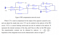
Ok taking one at a time, see if you can do a Bode analysis of the circuit in the attachment. That's one of the circuits you originally posted. The Bode analysis might make it clearer because that is a sort of approximation in itself.
You might also gain some insight if you do a complete frequency domain analysis of that circuit and make all of the resistors equal to "R" and all the capacitors equal to "C", and if that does not help, try making all of the resulting R=1 and C=1 and see if that makes more sense.
I am not sure I can find the time to go through the entire Maxim design process right now though.
NOTE:
It also appears that in the analysis they show they must have left out C9 and R6 by making them both equal to zero. That means R6=0 and C9 is left out of the circuit. You should try that with the Bode analysis.
 Facebook
 Google
 GitHub
 Linkedin
.png")