 Facebook
 Google
 GitHub
 Linkedin
Greetings everybody,
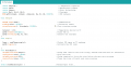
I am working on a simple infra-red heater projet, bassically the circuit uses a Zero-Crossing signal to control the firing of the triac, I can properly control the AC voltage through the load(Infra-red bulp) by simply controlling the delay prior to firing the triac.
I now have added a thermocoupler(MAX6675) and I want to make a PID that will varie the delay mentioned earlier based on the temperature of the MAX6675.
I inserted a picture of my code to this post, the only information that isn't included is the #define of all the pins && the PID library and some other unrelated stuff.
Here's where I am at right now, most of the examples I see use the PWM to trigger their Output, in my case it's a simple delay that would need to vary between 5000 and 8100 microSeconds, I am unsure as to how to proceed due to that difference, the Input in the other end seems more simple, the line I wrote is the following: Input = readThermocouple(); ... But again It's unclear to me as to how I can scale the Output (uS delay) with the temperature readings that'll probably range from 15c to 185c since this appliance is going to be used to pre-heat circuit boards.
Thanks in advance for reading this, I will literally be, forever grateful.
Attachments
-
 19 KB Views: 11


