PID Arduino Soldering Station - MOSFET

Thread Starter

mike_the_begginer

Joined Dec 7, 2019
137
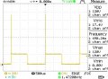
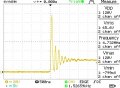
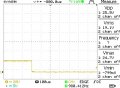
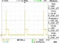
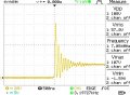
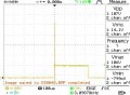
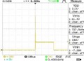
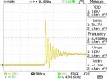
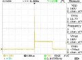
I connected the oscilloscope probe to Drain of the MOSFET.
DS0043 is the signal on the Drain, DS0044 is the rising edge of the Drain signal, DS0045 is the falling edge of the Drain signal.
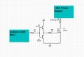
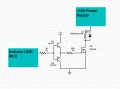
Measured using the push pull schematic (attached) for driving the MOSFET.
 

Attachments

ericgibbs

Joined Jan 29, 2010
21,527
hi,
If I am reading DS0043 correctly, the ON voltage is close to 0v.? if so the MOSFET is hard On.
Add a suppression diode across the load, the spike may damage the MOSFET.
E
 

Thread Starter

mike_the_begginer

Joined Dec 7, 2019
137
I have added a 1N4007 diode like in the attached schematic.
Please find attached the results from the oscilloscope (same probe connection as previous post).

Later Edit: I do not have any TVS diodes... only standard rectifier and FR107 and BY500/100.
The DS0050, DS0051 and DS0052 are with FR107 diode.
 

Attachments

Last edited:

Thread Starter

mike_the_begginer

Joined Dec 7, 2019
137
hi mike,
That diode should be clamping better than that DS0046 image shows.???
E

How are you powering the 24V.??
I don't know why is not clamping correctly.
The 24V are from a DIY linear power supply, variable from 0 to 25V and the current variable from 0 to 3 A. Currently, this PSU is set at 24V and 3A. It was built using LM324.

Later Edit: the Arduino is powered from the computer (USB). I have also tried with a 16V transformer with rectifier and 2x4700uF / 35V filter and the voltage spike also appeared at about the same voltage ~100V.

Second later edit: I am searching for a solution because I like this PID controlled soldering station and I want to build 2 stations, one for my workbench and one for backup. I also built some simpler schematics (without MCU) and I was not very happy with them.
 
Last edited:

Thread Starter

mike_the_begginer

Joined Dec 7, 2019
137
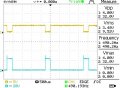
I used another mosfet - K1257 - and this time the voltage spike was not as high as when I used the previous mosfets.
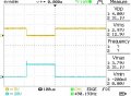
The yellow trace is the G of the K1257, and the blue trace is the D of the K1257.
This test was made powering the Arduino from the L7805 and not from the USB port of the computer.
I did not knew, but I was told that I need a logic level mosfet for this project. I will use logic level mosfet. In this case the push-pull transistor configuration (reply 23) is still needed ?
 

Attachments

Last edited:

Thread Starter

mike_the_begginer

Joined Dec 7, 2019
137
I want to make the soldering iron temperature to go up to 400 C. It is sufficient to modify the "350" value in the first and second "map" functions and then to calibrate the soldering station at shows in the original article ?
 
Top