Facebook
 Google
 GitHub
 Linkedin
Hello
I 'm not newbie about PICs, I did somethings with 16F690 and 18F2550 models before but I this 18F87K22 is very complicated for me since I 'm not expert, even not experinced so. I 'm using Pickit3 to program the device and it is successfull, however the device does not work as I expected, I wrote some led blink code to test it and I 'm masuring the output pin with multimeter but nothing.. I think my configuration is wrong or missing something.
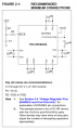
Can you help me please? I 'm trying to use internal oscillator at 16Mhz. I have all 100nF decoupling capacitor between vdd and vss pins included avdd and avss, not using on-chip regulator, ENVREG is not tied to VDD and VDDCORE is tied to ground with 100nF capacitor. It is not programmed if I missed something about the schematics according to the documentation already, I mean I 'm sure physical needs are ok otherwise it will not be programmed.
Thanks
Mod edit: code tags
I 'm not newbie about PICs, I did somethings with 16F690 and 18F2550 models before but I this 18F87K22 is very complicated for me since I 'm not expert, even not experinced so. I 'm using Pickit3 to program the device and it is successfull, however the device does not work as I expected, I wrote some led blink code to test it and I 'm masuring the output pin with multimeter but nothing.. I think my configuration is wrong or missing something.
Can you help me please? I 'm trying to use internal oscillator at 16Mhz. I have all 100nF decoupling capacitor between vdd and vss pins included avdd and avss, not using on-chip regulator, ENVREG is not tied to VDD and VDDCORE is tied to ground with 100nF capacitor. It is not programmed if I missed something about the schematics according to the documentation already, I mean I 'm sure physical needs are ok otherwise it will not be programmed.
Thanks
C:
/*
* File: main.c
* Author: ZAFER
*
* Created on 15 May?s 2016 Pazar, 20:25
*
* I2C Slave Device Sample
*
* NOTES:
*
*
*/
#define _XTAL_FREQ 16000000

#include <xc.h>
#include <stdio.h>
#include <stdlib.h>
#include <string.h>

#pragma config FOSC = INTIO2 // Oscillator (Internal RC oscillator)
#pragma config PLLCFG = OFF // PLL x4 Enable bit (Disabled)
#pragma config FCMEN = OFF // Fail-Safe Clock Monitor (Disabled)
#pragma config IESO = OFF // Internal External Oscillator Switch Over Mode (Disabled)
#pragma config WDTEN = OFF // Watchdog Timer (WDT disabled in hardware; SWDTEN bit disabled)
#pragma config XINST = OFF // Extended Instruction Set
#pragma config SOSCSEL = DIG // SOSC Power Selection and mode Configuration bits (Digital (SCLKI) mode)

int SLAVE_ADDR = 0x10;

void init(void);
void delayMS(int ms);

void main(void) {
     init();
     delayMS(500);

     while (1) {
          // Set activity led pin
          LATJbits.LATJ4 = PORTJbits.RJ4 == 0 ? 1 : 0;
          delayMS(500);
     }
     return;
}

void init() {

     // OSC
     OSCCONbits.IRCF0 = 1;
     OSCCONbits.IRCF1 = 1;
     OSCCONbits.IRCF2 = 1;
     OSCCONbits.HFIOFS = 1;
     OSCCONbits.SCS1 = 1;

     // Disable comparators
     CM1CONbits.CON = 0;
     CM2CONbits.CON = 0;
     CM3CONbits.CON = 0;

     // ANALOG INPUTS
     // Enable all analog inputs
     ANCON0 = 0xFF;
     ANCON1 = 0xFF;
     ANCON2 = 0xFF;

     // Set conversion as left justified and vref as AVREF+ and AVSS
     ADCON1bits.VCFG = 0b00;
     ADCON1bits.VNCFG = 0b0;
     ADCON2bits.ADFM = 0;

     // Set acquisition time for minimum requirements (14 TAD, ~16 TOSC)
     ADCON2bits.ADCS = 0b101;
     ADCON2bits.ACQT = 0b010;

     // I2C CONFIGURATION
     // Set as slave (SSPM(3:0) = 0110) as interrupt enabled
     SSP1CON1 = 0b00101110;

     // Set stretching enable
     SSP1CON2bits.SEN = 1;

     // Configure Input Levels and slew rate as I2C Standard Levels (Slew Rate control (SMP) set for 100kHz)
     SSP1STAT = 0b10000000;

     // Set i2c address to SLAVE_ADDR variable. Note that last bit of SSPADD is not used in 7 bit addressing mode
     SSP1ADD = SLAVE_ADDR << 1;

     // PORTS
     // Set address switch input port
     TRISB = 0b11111111;
     PORTB = 0;
     LATB = 0;

     // Set analog inputs ports. Note that sharp numbers shows input indices as starting from 1
     TRISAbits.TRISA1 = 1; // #1
     PORTA = 0;
     LATA = 0;

     TRISF = 0b11111111; // #2, #7, #8, #9, #10, #11, #12
     PORTF = 0;
     LATF = 0;

     TRISG = 0b11111111; // #13, #14, #15, #16
     PORTG = 0;
     LATG = 0;

     TRISH = 0b11111111; // #3, #4, #5, #6, #17, #18, #19, #20
     PORTH = 0;
     LATH = 0;

     // Set digital output ports
     TRISAbits.TRISA4 = 0; // #7
     TRISAbits.TRISA5 = 0; // #8
     PORTA = 0;
     LATA = 0;

     TRISCbits.TRISC1 = 0; // #6
     TRISCbits.TRISC2 = 0; // #4
     TRISCbits.TRISC7 = 0; // #5
     PORTC = 0;
     LATC = 0;

     TRISDbits.TRISD4 = 0; // #9
     TRISDbits.TRISD5 = 0; // #10
     TRISDbits.TRISD6 = 0; // #11
     TRISDbits.TRISD7 = 0; // #12
     PORTD = 0;
     LATD = 0;

     TRISEbits.TRISE4 = 0; // #20
     TRISEbits.TRISE5 = 0; // #19
     TRISEbits.TRISE6 = 0; // #18
     TRISEbits.TRISE7 = 0; // #17
     PORTE = 0;
     LATE = 0;

     TRISJ = 0b00000000; // #1, #2, #3, #13, #14, #15, #16 and activity led pin
     PORTJ = 0;
     LATJ = 0;

}
void delayMS(int ms){
     while(ms-- >= 0){
          __delay_ms(1);
     }
}
Last edited by a moderator: