Pic16f877a servo motor control by Timer0

Thread Starter

BurhanBhos

Joined Apr 4, 2019
14
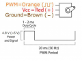
Hi! I am trying for 3 days to control basic servo motor (sg90) by using Pic16f877a by Timer0 in Mplab XC8 compiler.
Code:
#include <xc.h>
#include <stdint.h> 
#include "config.h"

#define _XTAL_FREQ 6000000

uint16_t counter = 0;
uint16_t on_time = 281, pwm_period_time = 3750;

void main(void) {
    TRISD = 0x00;
    PORTD = 0x00;
    
    PSA = 0;
    TMR0 = 252;
    T0CS = 0;
    //Prescaler
    PS0 = 0;
    PS1 = 0;
    PS2 = 0;
        
    TMR0IE = 1;
    TMR0IF = 0;
    PEIE = 1;
    GIE = 1;
    
    while(1);
}

void __interrupt() ISR()
{
    if(TMR0IF)
    {
        TMR0IF = 0;
        TMR0 = 252;
        //PORTDbits.RD0 = ~PORTDbits.RD0;
        if(counter == 0)
        {
            PORTDbits.RD0 = 1;
        }
        if(counter == on_time)
        {
            PORTDbits.RD0 = 0;
        }
        counter++;
        if(counter == pwm_period_time)
        {
            counter = 0;
        }
    }
}
I wrote this code based on my calculations which I attached. However, while it must give 90 degree, it always gives 180 degree in Proteus simulation and it doesn't work in real microcontroller also. However, when I tried with overflow time of 0.2ms I could get correct values for degrees of 0, 90, 45, 180. However, by value of 0.2ms I cannot get all of the values. Please, can you help me why it doesn't work? Am I miscalculating something?
 

Attachments

Picbuster

Joined Dec 2, 2013
1,047
Start to activate //PORTDbits.RD0 = ! PORTDbits.RD0;
Disable all outputs.

Take a scope and measure pin RD0
This is the basis of your system. This should produce a pulse allowing to produce all wanted values.

If not tweak the speed by modifying/reset int counter high byte.

Picbuster
PS Forget simulator.
 

Thread Starter

BurhanBhos

Joined Apr 4, 2019
14
Start to activate //PORTDbits.RD0 = ! PORTDbits.RD0;
Disable all outputs.

Take a scope and measure pin RD0
This is the basis of your system. This should produce a pulse allowing to produce all wanted values.

If not tweak the speed by modifying/reset int counter high byte.

Picbuster
PS Forget simulator.
Thank you for your fast response. I will give it a try and inform you :)
 

Thread Starter

BurhanBhos

Joined Apr 4, 2019
14
I did what you have said and noticed an interesting issue. The least overflow time I can obtain is 24.5 microseconds. However, calculations show that you can obtain as less as 5 microseconds. So, it is impossible to increase servo by one degree. Minimum you can do is 5 degree. Is there any other way of controlling servo with pic? Or do I have any problem with my code?
 

Thread Starter

BurhanBhos

Joined Apr 4, 2019
14
Interestingly, if I increase the oscillator frequency, for example 20Mhz, I could get 8 micro seconds. So, it means it is impossible to control servo motor precisely with pic microcontroller?
 

AlbertHall

Joined Jun 4, 2014
12,344
With that chip and a 20MHz clock, using the built-in PWM hardware you can get a 19.53kHz PWM with 10 bit resolution. This gives a time resolution for the PWM transistions of 50ns.
 

Ian Rogers

Joined Dec 12, 2012
1,136
Interestingly, if I increase the oscillator frequency, for example 20Mhz, I could get 8 micro seconds. So, it means it is impossible to control servo motor precisely with pic microcontroller?
Seriously?? The CCP module will give you a 10 bit resolution..

Whoops... Sorry Albert... I was typing when you responded!!
 

Thread Starter

BurhanBhos

Joined Apr 4, 2019
14
However, it is impossible to use CCP module for PWM, because I need 50Hz of PWM frequency which is impossible to get by using CCP module.
 

jpanhalt

Joined Jan 18, 2008
11,087
However, it is impossible to use CCP module for PWM, because I need 50Hz of PWM frequency which is impossible to get by using CCP module.
Are you sure you need 50 Hz? I have run ordinary model servos at 120 Hz using hardware PWM. Newer ones may go even higher. You only want four, fixed rotations. A delay for 45° paced with a timer interrupt (e.g, TMR0 or TMR2) would give you that.
 

MMcLaren

Joined Feb 14, 2010
861
However, it is impossible to use CCP module for PWM, because I need 50Hz of PWM frequency which is impossible to get by using CCP module.
Consider breaking up the 20-ms servo period into eighty 250-us PWM "frames" and use an interrupt "helper" to load the PWM duty cycle register for each upcoming "frame" and to refresh the servo pulse width from your 'servo' variable at the beginning of each servo period. Your servo variable would contain a value of 1000-2000 or 800-2200 or 750-2250, etc., with 1-us pulse width resolution.

Code:
;******************************************************************
;  interrupt vector                                               *
;******************************************************************
        org    0x0004
;
;  /* single servo example (16F1823, 16-MHz clock) */
;
;  void interrupt()            // 250-uS (1000 cycle) interrupts
;  { static int width = 0;     // width, typically 500..2500
;    static char frame = 1;    // # of 250-us PWM frames, 1..80
;    TMR2IF = 0;               // clear TMR2 interrupt flag
;    if(width >= 250)          // if width >= 250 usecs
;      CCPR1L = 250;           // use full 100% duty cycle
;    else                      // otherwise
;      CCPR1L = width;         // use balance of 'width'
;    width -= CCPR1L;          // update 'width' variable
;    if(--frame == 0)          // if end of 20-ms servo period
;    { frame = 80;             // reset for a new 20-ms period
;      width = servo;          // refresh 'width', 500..2500
;    }                         //
;  }                           //
;
 
Last edited:

MMcLaren

Joined Feb 14, 2010
861
Please, can you help me why it doesn't work? Am I miscalculating something?
It looks like you're trying to generate TMR0 interrupts every 8 instruction cycles (every 5.33 usecs). That's not going to happen. XC8 will add 30-32 instruction cycles to your ISR code just to save and restore processor context.

You might consider studying CCP module "compare" modes.

Good luck on your project.

Cheerful regards...
 
Last edited:

jpanhalt

Joined Jan 18, 2008
11,087
I did what you have said and noticed an interesting issue. The least overflow time I can obtain is 24.5 microseconds. However, calculations show that you can obtain as less as 5 microseconds. So, it is impossible to increase servo by one degree. Minimum you can do is 5 degree. Is there any other way of controlling servo with pic? Or do I have any problem with my code?
It's has been 3 days and no replies to questions or updates.

1) We do not know how the TS will enter the commands, if any, or whether he just wants to cycle between the defined positions of 0° to 180°.
2) What else, if anything will the MCU be doing?
3) Why does he believe the frame rate needs to be 50 Hz?
4) What servo is he using. That is relevant to the precision of positioning. For example, let's assume that the maximum servo sweep is 1.000 ms to 2.000 ms for 180°. That works out to be 5.6 us per degree. Inexpensive servos will have a deadband of at least 8 us. Thus, the command needs to change by more than that (sometimes much more) for the servo to register a change. What precision does he really need? Some modern servos are more precise.
 

Thread Starter

BurhanBhos

Joined Apr 4, 2019
14
Excuse me. I wasn't possible for me to check forum for several days. I have solved the problem with CCP1 compare mode and Timer1. I am using micro servo sg90. As you can see from picture I have uploaded I need 50Hz pwm period which is impossible by using Timer0 or just using Timers. And I want to get all the degrees, like (0,1,2,3,4,5...180).
 

Attachments

jpanhalt

Joined Jan 18, 2008
11,087
Glad you solved the problem. However, be aware that the 50 Hz thing is pretty much legacy from pre-digital when 8 channel was the best = 8 x 2.5 ms = 20 ms = 50 Hz. Today, one is not limited to 8 channels. Even 10 years ago, they operated well at 100 Hz.

Edit:
Here are a couple of relatively old references to using shorter refresh rates:
https://forum.allaboutcircuits.com/threads/servomotor-position-signal-max-frequency.42853/
https://www.helifreak.com/showthread.php?t=236406 (second post)

NB: a long time ago LONGER refresh rates were used to control servo speed (e.g., to make gear retraction more realistic). Much better programmed methods are available today.
 
Last edited:

Thread Starter

BurhanBhos

Joined Apr 4, 2019
14
Glad you solved the problem. However, be aware that the 50 Hz thing is pretty much legacy from pre-digital when 8 channel was the best = 8 x 2.5 ms = 20 ms = 50 Hz. Today, one is not limited to 8 channels. Even 10 years ago, they operated well at 100 Hz.

Edit:
Here are a couple of relatively old references to using shorter refresh rates:
https://forum.allaboutcircuits.com/threads/servomotor-position-signal-max-frequency.42853/
https://www.helifreak.com/showthread.php?t=236406 (second post)

NB: a long time ago LONGER refresh rates were used to control servo speed (e.g., to make gear retraction more realistic). Much better programmed methods are available today.
Thank you very much :)
 
Top