Hx711 with pic16f877A

Thread Starter

Michel09

Joined May 23, 2024
20
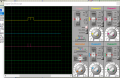
Hi guys, I have a project that I have to finish as soon as possible. I am new and I find your forum very interesting. In fact, I want to make a digital weighing indicator. And I started by wanting to interface the hx711 module with a pic16f877A. I generated the code in mikroC and then directed the file. Hex under proteus with the diagram I made. But alas, nothing works. I don't know if my code has a problem since I used the reference C code put in the hx711 datasheet.
I need your help please
I have attached my c code and diagramschema.png
 

Attachments

geekoftheweek

Joined Oct 6, 2013
1,429
One trick that I found that helps with everything is make an LED blink first then start adding more code. When the LED stops blinking look through the latest changes and you should find the problem.

Edit...

I had an answer based on the waveforms shown in the datasheet, but then realized there is a bit more to the puzzle that I missed. Unfortunately I have to get going and don't have time. If nobody else gets to it, I'll try to explain the datasheet example a bit tomorrow to help out.
 
Last edited:

ericgibbs

Joined Jan 29, 2010
21,390
Hi,
The Equation using your values is, 1.25v(28.2/20K) =1.76V on the bridge.

I would suggest for testing you use the 5V direct to the bridge.[ no transistor]

E
AD amp.pngEG57_ 1767.png
 

ericgibbs

Joined Jan 29, 2010
21,390
Hi M,
This image shows the waveforms you should see on your scope.
It appears your code and libs are at fault,
Try writing a simple LED program as shown in post #2
E
HX711timing1.gif
 

Thread Starter

Michel09

Joined May 23, 2024
20
I readjusted the oscilloscope parameters for the case of the hx711 and here are the curves in yellow which are the clock and in red the data output
 

Attachments

ericgibbs

Joined Jan 29, 2010
21,390
Hi M,
Those waveforms you have posted are not correct, the clock should be as post #12.
I would say the lib files in your program are not working as you expect.

E
This is an example of the Header files in Arduino.
// Include application, user and local libraries
//Edited and TFT added 260918EG

#include "SPI.h"
#include "TFT_22_ILI9225.h"

#include "HX711.h"


// HX711.DOUT - pin #A1
// HX711.PD_SCK - pin #A0

// parameter "gain" is ommited; the default value 128 is used by the library
HX711 scale(A1, A0);

String hxString ="";
float weight = 0;


Update:
These are the Header files from that link I posted,

#define __USE_C99_MATH

#include <stdbool.h>
#include <stdint.h>
#include <avr/io.h>
#include <util/delay.h>
#include "HX711.h"
 
Last edited:

Thread Starter

Michel09

Joined May 23, 2024
20
thank you for your help really but I don't understand how an avr syntax can help me with my pic16f877A. I'm not very knowledgeable in microcontroller architecture. hence my question
 

MrChips

Joined Oct 2, 2009
34,626
The example code is written in C. It doesn’t matter if the target processor is Microchip PIC or Atmel AVR except for hardware related dependencies.
 
Top