Facebook
 Google
 GitHub
 Linkedin
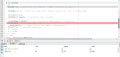
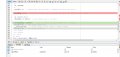
@JohnInTX Which code is working on the simulator?FWIW: I verified in the simulator that you get an interrupt every 2166 counts of TIMER1 then it resets and begins again.
To do this, I used the 'real' code, .
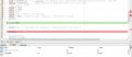
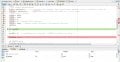
CCP1CON =0b00001011;In #218 You aren’t configuring CCP1 for compare..
What's wrong with this ?