PIC16F1615 simply won't blink

Thread Starter

StrongPenguin

Joined Jun 9, 2018
307
While I'm waiting for my Curiosity HPC, I'm trying to get this thing to blink. No success. I had a somewhat good run with MSP430, but PIC is not giving me any slack. I suspect that I am not using the software right, as I can not say anything wrong with the code.

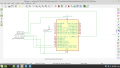
I'm not using an external crystal, but I've it to run on the internal one. The setup is just the Pickit3 hooked up to the respective pins on the PIC16F1615. The attached image shows another MCU, since the one in use was not in the KiCad library.

When I flash the code, I just hit "Build Main Project" (F11), the hammer icon. It compiles, but says "ProjectLocation.production.hex does not exist", yet still I get build successful. I think I've seen in videos, when one compiles, the XC8 compiler runs in the background, but I can't find and executable file for the compiler to open, and I've not had any luck finding a compiler user guide. One funny thing is that if I pull the pins out of the Pickit3, it still says build successful.

Any thoughts?

NOTE: The led and the resistor are in opposite order on my board. Everything is checked and double checked.

Code:
/* 
 * File:   main.c
 * Author: 
 *
 * Created on November 7, 2019, 8:50 PM
 */

#include <stdio.h>
#include <stdlib.h>
#include <xc.h>
#include "newxc8_header.h"

#define _XTAL_FREQ 8000000

//BEGIN CONFIG
#pragma config FOSC = INTOSC // Oscillator Selection bits (HS oscillator)
#pragma config WDTE = ON // Watchdog Timer Enable bit (WDT enabled)
#pragma config PWRTE = OFF // Power-up Timer Enable bit (PWRT disabled)
#pragma config BOREN = ON // Brown-out Reset Enable bit (BOR enabled)
#pragma config LVP = OFF // Low-Voltage (Single-Supply) In-Circuit Serial Programming Enable bit (RB3 is digital I/O, HV on MCLR must be used for programming)
//#pragma config CPD = OFF // Data EEPROM Memory Code Protection bit (Data EEPROM code protection off)
#pragma config WRT = OFF // Flash Program Memory Write Enable bits (Write protection off; all program memory may be written to by EECON control)
#pragma config CP = OFF // Flash Program Memory Code Protection bit (Code protection off)
//END CONFIG

int main()
{
  TRISA4 = 0; //RB0 as Output PIN
  while(1)
  {
    RA4 = 1;  // LED ON
    __delay_ms(1000); // 1 Second Delay
    RA4 = 0;  // LED OFF
    __delay_ms(1000); // 1 Second Delay
  }
  return 0;
}
 

Attachments

nerdegutta

Joined Dec 15, 2009
2,684
Hi.

I copy/paste your code into my MPLAB X v5.10, with XC8 v2.05.

When I hit the "hammer" icon, the first error was '#include "newxc8_header.h"' I don't have that library so I commented that out.

Next was the TRISA4 declaration. I removed the number 4 so it says "TRISA = 0;"

Then I changed the "RA4 = 1;" and "RA4 = 0"; to PORTAbits.RA4 = 1 and PORTAbits.RA4 = 0.

Then it compiled without any errors.

I do believe you missing a 4.7-10K resistor between MCLR and VDD.

Flashing a LED is the Hello world version in embedded programming and circuit design. :)
 

JohnInTX

Joined Jun 26, 2012
4,787
Also:
Your watchdog timer WDT is enabled but you are not clearing it so the PIC will reset periodically.
You should write to LATA, not PORTA.
Haven't checked on actual hardware..

EDIT: your config #pragmas are incomplete. In MPLABX select Window->Target Memory Views ->Configuration Bits. An interactive window will open. Review and select each option then click Generate Source Code to Output. Copy and paste from the Output Window to your source code. Just guessing but I get this (note that the Curiosity Boards need LVP enabled - update to fit your hardware including MCLR/ pullup)
C:
/*
* File:   main.c
* Author:
*
* Created on November 7, 2019, 8:50 PM
*/

// PIC16F1615 Configuration Bit Settings

// 'C' source line config statements

// CONFIG1
#pragma config FOSC = INTOSC    // Oscillator Selection Bits (INTOSC oscillator: I/O function on CLKIN pin)
#pragma config PWRTE = OFF      // Power-up Timer Enable (PWRT disabled)
#pragma config MCLRE = ON       // MCLR Pin Function Select (MCLR/VPP pin function is MCLR)
#pragma config CP = OFF         // Flash Program Memory Code Protection (Program memory code protection is disabled)
#pragma config BOREN = OFF      // Brown-out Reset Enable (Brown-out Reset disabled)
#pragma config CLKOUTEN = OFF   // Clock Out Enable (CLKOUT function is disabled. I/O or oscillator function on the CLKOUT pin)
#pragma config IESO = OFF       // Internal/External Switch Over (Internal External Switch Over mode is disabled)
#pragma config FCMEN = ON       // Fail-Safe Clock Monitor Enable (Fail-Safe Clock Monitor is enabled)

// CONFIG2
#pragma config WRT = OFF        // Flash Memory Self-Write Protection (Write protection off)
#pragma config PPS1WAY = ON     // Peripheral Pin Select one-way control (The PPSLOCK bit cannot be cleared once it is set by software)
#pragma config ZCD = OFF        // Zero Cross Detect Disable Bit (ZCD disable.  ZCD can be enabled by setting the ZCDSEN bit of ZCDCON)
#pragma config PLLEN = OFF      // PLL Enable Bit (4x PLL is enabled when software sets the SPLLEN bit)
#pragma config STVREN = ON      // Stack Overflow/Underflow Reset Enable (Stack Overflow or Underflow will cause a Reset)
#pragma config BORV = LO        // Brown-out Reset Voltage Selection (Brown-out Reset Voltage (Vbor), low trip point selected.)
#pragma config LPBOR = OFF      // Low-Power Brown Out Reset (Low-Power BOR is disabled)
#pragma config LVP = ON         // Low-Voltage Programming Enable (Low-voltage programming enabled)

// CONFIG3
#pragma config WDTCPS = WDTCPS1F// WDT Period Select (Software Control (WDTPS))
#pragma config WDTE = OFF       // Watchdog Timer Enable (WDT disabled)
#pragma config WDTCWS = WDTCWSSW// WDT Window Select (Software WDT window size control (WDTWS bits))
#pragma config WDTCCS = SWC     // WDT Input Clock Selector (Software control, controlled by WDTCS bits)

// #pragma config statements should precede project file includes.
// Use project enums instead of #define for ON and OFF.

#include <xc.h>


int main()
{
  TRISA = 0; //PORTA as Output PIN
  while(1)
  {
    LATA4 = 1;  // LED ON
    __delay_ms(1000); // 1 Second Delay
    LATA4 = 0;  // LED OFF
    __delay_ms(1000); // 1 Second Delay
  }
  return 0;
}
 
Last edited:

ArakelTheDragon

Joined Nov 18, 2016
1,362
I had this problem when I started with "XC8" recently also. "XC8" is professional compiler, it requires deep understanding of the processor(meaning you have to read the datasheet). Your problem is first the mistakes in the code and then you did not set the analog registers correctly. By default on "power on" the analog modules are on and the pins can not be used as digital. Also "pin MCLR" is only input on some processors. Still this is the best compiler on the market, but it requires work to understand the "PIC microcontroller", after that things become easy and with no mistakes.
 

Thread Starter

StrongPenguin

Joined Jun 9, 2018
307
It compiles! It compiles! Now I just have to figure out why
:p
I have the 16F1615 datasheet, which is 597 pages. This is the one I should stick with, right? In MSP430, I had one User Guide at 650'something pages, and a datasheet at 70 pages, or so. I don't wanna spend time with the wrong sheet. Guess I should start with reading about the architecture and then the I/O chapter.

@nerdegutta I seems to work without the 10k res, but I could try to add it just for giggles.

Thanks for the help, all

Code:
/*
* File:   main.c
* Author:
*
* Created on November 7, 2019, 8:50 PM
*/

// PIC16F1615 Configuration Bit Settings

// 'C' source line config statements

// CONFIG1
#pragma config FOSC = INTOSC    // Oscillator Selection Bits (INTOSC oscillator: I/O function on CLKIN pin)
#pragma config PWRTE = OFF      // Power-up Timer Enable (PWRT disabled)
#pragma config MCLRE = ON       // MCLR Pin Function Select (MCLR/VPP pin function is MCLR)
#pragma config CP = OFF         // Flash Program Memory Code Protection (Program memory code protection is disabled)
#pragma config BOREN = OFF      // Brown-out Reset Enable (Brown-out Reset disabled)
#pragma config CLKOUTEN = OFF   // Clock Out Enable (CLKOUT function is disabled. I/O or oscillator function on the CLKOUT pin)
#pragma config IESO = OFF       // Internal/External Switch Over (Internal External Switch Over mode is disabled)
#pragma config FCMEN = ON       // Fail-Safe Clock Monitor Enable (Fail-Safe Clock Monitor is enabled)

// CONFIG2
#pragma config WRT = OFF        // Flash Memory Self-Write Protection (Write protection off)
#pragma config PPS1WAY = ON     // Peripheral Pin Select one-way control (The PPSLOCK bit cannot be cleared once it is set by software)
#pragma config ZCD = OFF        // Zero Cross Detect Disable Bit (ZCD disable.  ZCD can be enabled by setting the ZCDSEN bit of ZCDCON)
#pragma config PLLEN = OFF      // PLL Enable Bit (4x PLL is enabled when software sets the SPLLEN bit)
#pragma config STVREN = ON      // Stack Overflow/Underflow Reset Enable (Stack Overflow or Underflow will cause a Reset)
#pragma config BORV = LO        // Brown-out Reset Voltage Selection (Brown-out Reset Voltage (Vbor), low trip point selected.)
#pragma config LPBOR = OFF      // Low-Power Brown Out Reset (Low-Power BOR is disabled)
#pragma config LVP = ON         // Low-Voltage Programming Enable (Low-voltage programming enabled)

// CONFIG3
#pragma config WDTCPS = WDTCPS1F// WDT Period Select (Software Control (WDTPS))
#pragma config WDTE = OFF       // Watchdog Timer Enable (WDT disabled)
#pragma config WDTCWS = WDTCWSSW// WDT Window Select (Software WDT window size control (WDTWS bits))
#pragma config WDTCCS = SWC     // WDT Input Clock Selector (Software control, controlled by WDTCS bits)

// #pragma config statements should precede project file includes.
// Use project enums instead of #define for ON and OFF.

#define _XTAL_FREQ 1000000

#include <xc.h>


int main()
{
  TRISA = 0; //PORTA as Output PIN
  while(1)
  {
    LATA4 = 1;  // LED ON
    __delay_ms(1000); // 1 Second Delay
    LATA4 = 0;  // LED OFF
    __delay_ms(1000); // 1 Second Delay
  }
  return 0;
}
 

JohnInTX

Joined Jun 26, 2012
4,787
In Project Properties select PICKit 3 as the debugger, Build for Debugging and step the code. Open a watch window to view the ports (SFR window) and see the port bits working. CLick the left edge of the source window to toggle breakpoints.
 

Thread Starter

StrongPenguin

Joined Jun 9, 2018
307
"DoBlink.X.debug.elf does not exist" - that's the only thing I get. Same as with the .hex which didn't exist before. Is it not self supposed to create a debug file?
 

jpanhalt

Joined Jan 18, 2008
11,087
Let's start with what chip you are using. Do you know?

The title says 16F1615
Your schematic says: 16F1518

They are not identical, so far as I can tell.

1577576736725.png

Now, the PIC16F16F1615 is this:

1577577299977.png


It seems RA 4 jumps around. What chip are you really using and to what pin is the LED attached? It may make a difference. ;)
Dyslexia strike again?
 
Last edited:

AlbertHall

Joined Jun 4, 2014
12,345
You need to add the line
ANSELA = 0;
as the first line in main. Without this port A will only work as analog - it will ignore all digital input or output.
 

JohnInTX

Joined Jun 26, 2012
4,787
You need to add the line
ANSELA = 0;
as the first line in main. Without this port A will only work as analog - it will ignore all digital input or output.
I wondered how I missed that but @jpanhalt notes two different part numbers in play here. RA4 on the 16F1518 is not an analog input. It is on the 16F1615. Good catch.
 

JohnInTX

Joined Jun 26, 2012
4,787
"DoBlink.X.debug.elf does not exist" - that's the only thing I get. Same as with the .hex which didn't exist before. Is it not self supposed to create a debug file?
On the MPLABX toolbar, mouse over until you see Debug Main Project (it's not the same as Build for Debug). Click that and it will build for debugging and automatically load the program into the PK3 (assuming you have it set as the Hardware Tool in Project Properties) and run the code automatically. Run everything out of the MPLABX IDE, work within a project and be sure that the project is set to be the Main Project.

Set a breakpoint at the second output operation. If it gets there, you know the PIC is running. If not, visit the hardware. Note that PK3 will manage MCLR/ for itself but you still need a pullup. Note also that debugging runs on the PIC natively i.e. the PIC hardware has to be wired correctly.

When you get your Curiosity HPC be sure to change the processor to match (if necessary) and change the Hardware Tool to 'Curiosity PKOB'. You can create different setups for the same project if you expect to switch back and forth.

Sounds like you're having fun.
 

geekoftheweek

Joined Oct 6, 2013
1,201
A couple things I had to learn the hard way...

Disable low voltage programming in the configuration settings unless you actually plan on using it, or pull that pin down otherwise you may enter low voltage programming mode and it will have you beating your head against the wall.

When you start to work with the built in peripherals make sure you set the pin selection registers where applicable. The datasheets seem to show default locations for things, but the couple I have played with that have pins that can be remapped are not set to default locations.

You have the right datasheet. It's nice and long, but once you learn the layout you'll figure out what is important and what isn't for what you want to do. Luckily C programming eliminates a lot of the memory related stuff, but it will be good to know in the long run.

They are fun. Good luck!
 
Top