Facebook
 Google
 GitHub
 Linkedin
Hi dear,
i need you help with programming the pic using c language .
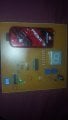
this is what i have to do using the pickit 3
1) A positive-going pulse every crank revolution for the fuel injector whose length can be varied between approximately 500 us and 8 ms in 256 steps by use of one of the two potentiometer controls provided on the demonstration board pic-kit3
2)A positive-going pulse every crank revolution for the spark ignition. The pulse should be approximately 2 ms long and the falling edge of this pulse is assumed to generate the spark with minimal delay. The position of this negative firing edge should be variable from approximately 84° before top-dead-centre (BTDC) to 12° after top-dead-centre. The method of varying the firing position will also be by turning one of the potentiometers on the board and will provide 32 different firing positions with a resolution of 3°. Note that sparks will be generated on both TDC positions of the four-stroke cycle and the missing teeth on the “Toothed Wheel simulator” occur 120° BTDC
this is what i have done so far:
please help me because i have no idea what i am doing
thank you
i need you help with programming the pic using c language .
this is what i have to do using the pickit 3
1) A positive-going pulse every crank revolution for the fuel injector whose length can be varied between approximately 500 us and 8 ms in 256 steps by use of one of the two potentiometer controls provided on the demonstration board pic-kit3
2)A positive-going pulse every crank revolution for the spark ignition. The pulse should be approximately 2 ms long and the falling edge of this pulse is assumed to generate the spark with minimal delay. The position of this negative firing edge should be variable from approximately 84° before top-dead-centre (BTDC) to 12° after top-dead-centre. The method of varying the firing position will also be by turning one of the potentiometers on the board and will provide 32 different firing positions with a resolution of 3°. Note that sparks will be generated on both TDC positions of the four-stroke cycle and the missing teeth on the “Toothed Wheel simulator” occur 120° BTDC
this is what i have done so far:
C:
#include <xc.h>
#include <timers.h>
#include <adc.h>

// Configuration settings
#pragma config OSC=HS,FSCM=OFF,IESO=OFF
#pragma config PWRT=ON,BOR=OFF,BORV=45
#pragma config WDT=OFF
#pragma config MCLRE=ON
#pragma config STVR=OFF,LVP=OFF,DEBUG=OFF
#pragma config CP0=OFF,CP1=OFF
#pragma config CPB=OFF,CPD=OFF
#pragma config WRT0=OFF,WRT1=OFF
#pragma config WRTB=OFF,WRTC=OFF,WRTD=OFF
#pragma config EBTR0=OFF,EBTR1=OFF
#pragma config EBTRB=OFF
//===============================================================

void    main(void)
{
void OpenTimer0 (unsigned char);
void WriteTimer0(unsigned int timer0);
void CloseTimer0 (void);


// unsigned char ReadADCValues(void);


     OSCCONbits.SCS0=0;     //set oscillator to external
    OSCCONbits.SCS1=0;

    TRISA = 0b00110011;        //Set port input output directions
    TRISB = 0b11000100;
    ADCON1 = 0b11111100;    //All bits digital I/O except AN0 and AN1
    RCON=0b00000000;        //disable interrupt priorities (compatible with 16F series)
    INTCON=0b00000000;        //disable interrupts
    INTCON2=0b00000000;     //pull-ups enabled interrupt are all low priority

//    OpenADC(    ADC_FOSC_16 & ADC_LEFT_JUST & ADC_8_TAD,
//            ADC_CH0 & ADC_INT_OFF & ADC_VREFPLUS_VDD,
//            0b01111110 ); //ADCON1 - AN0 set as analogue in
//    ADCON0bits.VCFG1=0;//Discovered bug - OpenADC left this bit set leaving AVSS as external vref which is connected to an LED!


OpenTimer0(    TIMER_INT_OFF    & //no timer interrupts
            T0_16BIT        & //16 bit mode
            T0_SOURCE_INT    &
            T0_EDGE_FALL    & //Not important for this
            T0_PS_1_64           // divide by 64 prescaler
            );

    WriteTimer0(0);
    INTCONbits.TMR0IF=0;


    unsigned int readtimervalue;


    while(1)    //Loop forever
    {

        while(PORTBbits.RB2==0); //wait until pulse goes high
        WriteTimer0(0);
        while(PORTBbits.RB2==1);// wait until the pulse goes low
        readtimervalue = ReadTimer0();
        while(PORTBbits.RB2==0);


           ????

    }

    CloseTimer0();

//    CloseADC(); // Not actually used but placed here so you know the function exists!

}

void OpenTimer0 (unsigned char config)
{

T0CON = (0X7f & config);
TMR0H = 0;
TMR0L = 0;

INTCONbits.TMR0IF = 0;

if(config&0x80)

INTCONbits.TMR0IE = 1;
else
INTCONbits.TMR0IE = 0;

T0CONbits.TMR0ON = 1;
}

void WriteTimer0(unsigned int timer0)
{
union Timers timer;
timer.lt = timer0;

TMR0H = timer.bt[1];
TMR0L = timer.bt[0];
}

void CloseTimer0 (void)
{
T0CONbits.TMR0ON = 0;
INTCONbits.TMR0IE = 0;

}

unsigned int ReadTimer0(void)
{
  union Timers timer;

  timer.bt[0] = TMR0L;  // Copy Timer0 low byte into union
  timer.bt[1] = TMR0H;  // Copy Timer0 high byte into union

  return (timer.lt);    // Return the int
}


//unsigned char ReadADCValues(void)
//{
//
//        ConvertADC();
//        while(BusyADC());
//        return ADRESH;//Returns 8 MSB of 10 bit result
//}
//
//void ConvertADC(void)
//{
//  ADCON0bits.GO = 1;
//}
//
////note ADC_V3
//void OpenADC( unsigned char config,
//              unsigned char config2,
//              unsigned char portconfig)
//{
//    ADCON0 = 0;
//    ADCON2 = 0;
//
//    ADCON0 = ((config2 >> 1) & 0b00111100) |
//             ((config2 << 6) & 0b11000000);
//    ADCON1 = portconfig;
//    ADCON2 = ((config & 0b10000000)|((config >> 4) & 0b00000111)) |
//             ((config << 2) & 0b00111000);
//
//    if( config2 & 0b10000000 )
//    {
//      PIR1bits.ADIF = 0;
//      PIE1bits.ADIE = 1;
//      INTCONbits.PEIE = 1;
//    }
//    ADCON0bits.ADON = 1;
//}
//
//char BusyADC(void)
//{
//  return(ADCON0bits.GO);
//}
//
//void CloseADC(void)
//{
//  ADCON0bits.ADON = 0;
//  PIE1bits.ADIE = 0;
//}

please help me because i have no idea what #include <xc.h>
#include <timers.h>
#include <adc.h>

// Configuration settings
#pragma config OSC=HS,FSCM=OFF,IESO=OFF
#pragma config PWRT=ON,BOR=OFF,BORV=45
#pragma config WDT=OFF
#pragma config MCLRE=ON
#pragma config STVR=OFF,LVP=OFF,DEBUG=OFF
#pragma config CP0=OFF,CP1=OFF
#pragma config CPB=OFF,CPD=OFF
#pragma config WRT0=OFF,WRT1=OFF
#pragma config WRTB=OFF,WRTC=OFF,WRTD=OFF
#pragma config EBTR0=OFF,EBTR1=OFF
#pragma config EBTRB=OFF
//===============================================================

void    main(void)
{
void OpenTimer0 (unsigned char);
void WriteTimer0(unsigned int timer0);
void CloseTimer0 (void);


// unsigned char ReadADCValues(void);


     OSCCONbits.SCS0=0;     //set oscillator to external
    OSCCONbits.SCS1=0;

    TRISA = 0b00110011;        //Set port input output directions
    TRISB = 0b11000100;
    ADCON1 = 0b11111100;    //All bits digital I/O except AN0 and AN1
    RCON=0b00000000;        //disable interrupt priorities (compatible with 16F series)
    INTCON=0b00000000;        //disable interrupts
    INTCON2=0b00000000;     //pull-ups enabled interrupt are all low priority

//    OpenADC(    ADC_FOSC_16 & ADC_LEFT_JUST & ADC_8_TAD,
//            ADC_CH0 & ADC_INT_OFF & ADC_VREFPLUS_VDD,
//            0b01111110 ); //ADCON1 - AN0 set as analogue in
//    ADCON0bits.VCFG1=0;//Discovered bug - OpenADC left this bit set leaving AVSS as external vref which is connected to an LED!


OpenTimer0(    TIMER_INT_OFF    & //no timer interrupts
            T0_16BIT        & //16 bit mode
            T0_SOURCE_INT    &
            T0_EDGE_FALL    & //Not important for this
            T0_PS_1_64           // divide by 64 prescaler
            );

    WriteTimer0(0);
    INTCONbits.TMR0IF=0;


    unsigned int readtimervalue;


    while(1)    //Loop forever
    {

        while(PORTBbits.RB2==0); //wait until pulse goes high
        WriteTimer0(0);
        while(PORTBbits.RB2==1);// wait until the pulse goes low
        readtimervalue = ReadTimer0();
        while(PORTBbits.RB2==0);


           ????

    }

    CloseTimer0();

//    CloseADC(); // Not actually used but placed here so you know the function exists!

}

void OpenTimer0 (unsigned char config)
{

T0CON = (0X7f & config);
TMR0H = 0;
TMR0L = 0;

INTCONbits.TMR0IF = 0;

if(config&0x80)

INTCONbits.TMR0IE = 1;
else
INTCONbits.TMR0IE = 0;

T0CONbits.TMR0ON = 1;
}

void WriteTimer0(unsigned int timer0)
{
union Timers timer;
timer.lt = timer0;

TMR0H = timer.bt[1];
TMR0L = timer.bt[0];
}

void CloseTimer0 (void)
{
T0CONbits.TMR0ON = 0;
INTCONbits.TMR0IE = 0;

}

unsigned int ReadTimer0(void)
{
  union Timers timer;

  timer.bt[0] = TMR0L;  // Copy Timer0 low byte into union
  timer.bt[1] = TMR0H;  // Copy Timer0 high byte into union

  return (timer.lt);    // Return the int
}


//unsigned char ReadADCValues(void)
//{
//
//        ConvertADC();
//        while(BusyADC());
//        return ADRESH;//Returns 8 MSB of 10 bit result
//}
//
//void ConvertADC(void)
//{
//  ADCON0bits.GO = 1;
//}
//
////note ADC_V3
//void OpenADC( unsigned char config,
//              unsigned char config2,
//              unsigned char portconfig)
//{
//    ADCON0 = 0;
//    ADCON2 = 0;
//
//    ADCON0 = ((config2 >> 1) & 0b00111100) |
//             ((config2 << 6) & 0b11000000);
//    ADCON1 = portconfig;
//    ADCON2 = ((config & 0b10000000)|((config >> 4) & 0b00000111)) |
//             ((config << 2) & 0b00111000);
//
//    if( config2 & 0b10000000 )
//    {
//      PIR1bits.ADIF = 0;
//      PIE1bits.ADIE = 1;
//      INTCONbits.PEIE = 1;
//    }
//    ADCON0bits.ADON = 1;
//}
//
//char BusyADC(void)
//{
//  return(ADCON0bits.GO);
//}
//
//void CloseADC(void)
//{
//  ADCON0bits.ADON = 0;
//  PIE1bits.ADIE = 0;
//}thank you