Photomultiplier amplifier circuit

Thread Starter

Alvin_freeman

Joined Sep 23, 2022
21
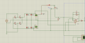
I add R8 for making a negative signal, and I add 1/2VCC because author of circuit in the first post add too.( sorry I am not electronic engineer.) So I can make mistakes. I am learning
 

sghioto

Joined Dec 31, 2017
5,392
You don't seem to understand what I'm saying. R8 should be 50 ohms and there should not be a connection from the cathode of D2 to the 1/2 Vcc junction of R6-R7.
 

Thread Starter

Alvin_freeman

Joined Sep 23, 2022
21
You don't seem to understand what I'm saying. R8 should be 50 ohms and there should not be a connection from the cathode of D2 to the 1/2 Vcc junction of R6-R7.
Okay, did you see first had drawn schematic. I have a question why he add 1/2 VCC to the cathode of photodiode. Why R8 should be 50 ohms? There is no r8 in the original schematic I add it to schematic.
 

sghioto

Joined Dec 31, 2017
5,392
The data sheet for D2 shows using a 50 ohm resistor where you added R8. Adding R8 is fine but try changing the value to 50 ohms in the simulation.
Looking at the first drawing there should not be a connection from the cathode of D2 to the 1/2 Vcc. I don't know why he showed that.
In your schematic in post #19 you should remove the connection from the cathode of D2 to the junction of R6-R7.
 
Last edited:

MrChips

Joined Oct 2, 2009
30,824
If you are going to do the simulation start off with using a bipolar supply and bipolar opamp just to get things working. We can modify the circuit at a later time.
 

Thread Starter

Alvin_freeman

Joined Sep 23, 2022
21
The data sheet for D2 shows using a 50 ohm resistor where you added R8. Adding R8 is fine but try changing the value to 50 ohms in the simulation.
Looking at the first drawing there should not be a connection from the cathode of D2 to the 1/2 Vcc. I don't know why he showed that.
In your schematic in post #19 you should remove the connection from the cathode of D2 to the junction of R6-R7.
I did what you said before, removing or adding R8 or connection you said before didn't change anything.
 

Thread Starter

Alvin_freeman

Joined Sep 23, 2022
21
If you are going to do the simulation start of with using a bipolar supply and bipolar opamp just to get things working. We can modify the circuit at a later time.
I will try bipolar supply but I don't know my Opamp is bipolar or not there is no information about it. maybe all are unipolar!!!
 

MrChips

Joined Oct 2, 2009
30,824
I will try bipolar supply but I don't know my Opamp is bipolar or not there is no information about it. maybe all are unipolar!!!
If you select a generic opamp from the library and there are 5 pins with two showing Vcc+ and Vcc- or V+ and V- then it is bipolar.

Select a FET input opamp such as TL071.
 

Thread Starter

Alvin_freeman

Joined Sep 23, 2022
21
If you select a generic opamp from the library and there are 5 pins with two showing Vcc+ and Vcc- or V+ and V- then it is bipolar.

Select a FET input opamp such as TL071.
I didn't find VCC in my simulator, but I add bipolar power supply and TL071. this time I get different signal shape but I don't know which one was correct. Square waves? which I get before or Sine wave.
 

Attachments

MrChips

Joined Oct 2, 2009
30,824
I am not at a desktop PC and can only enter posts via an iPad.
You do not need a sinewave or fullwave rectifier circuit.

Connect V+ and V- supplies directly to the opamp.

Remove the Si diode. You will simulate the detector signal with a short duration positive or negative pulse as I introduced in post #17.
 

Thread Starter

Alvin_freeman

Joined Sep 23, 2022
21
I am not at a desktop PC and can only enter posts via an iPad.
You do not need a sinewave or fullwave rectifier circuit.

Connect V+ and V- supplies directly to the opamp.

Remove the Si diode. You will simulate the detector signal with a short duration positive or negative pulse as I introduced in post #17.
You mean I must remove all rectifier diodes and put AC voltage directly to the Opamp?! I did it. and I add an VPULSE generator.
 

Attachments

sghioto

Joined Dec 31, 2017
5,392
I think this is what MrChips was suggesting.
In this circuit I'm using a LM2904 you had in your previous circuit. The LM2904 is a dual op amp and by connecting the signal to the positive input will only require 2 stages. Notice the polarity of the 9 volt batteries on pins 4 and 8. U1A is set for a gain of 101 followed by the filter/buffer U1B
1664127962863.png
 
Last edited:

sghioto

Joined Dec 31, 2017
5,392
I agree with MrChips based on the input waveform. The problem is trying to simulate what the output from the actual sensor should look like in my opinion.
 

Thread Starter

Alvin_freeman

Joined Sep 23, 2022
21
I agree with MrChips based on the input waveform. The problem is trying to simulate what the output from the actual sensor should look like in my opinion.
Those results are actually promising.
Why do you say something is wrong?
I don't know but I tried to put a negative small pulse like real pulse and I expect an positive wide pulse on the output. I think small changes on input pulse maybe affect hugely output.
 
Top