Photomultiplier amplifier circuit

Thread Starter

Alvin_freeman

Joined Sep 23, 2022
21
Hi I am new here, I don't know too much about circuits.
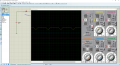
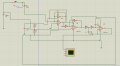
I want to make that hand drew schematics but when I simulate it in Proteus it doesn't work(there is no signal or no positive wide signal). I don't know what I did wrong? maybe everything, lol
 

Attachments

sghioto

Joined Dec 31, 2017
5,376
For one you have 43 volts connected directly to the - input of U2 and U3. Remove the connection from the + side of BAT 2 to the junction of R6 and R7. Why do you need 43 volts to bias the D2?
 
Last edited:

Thread Starter

Alvin_freeman

Joined Sep 23, 2022
21
For one you have 43 volts connected directly to the - input of U2 and U3. Remove the connection from the + side of BAT 2 to the junction of R6 and R7. Why do you need the 43 volt battery?
Because in the input we have 43 volt photomultiplier and I want to detect and amplify signals from it. I didn't draw this circuit, just I want to make it. I know about circuit making and designs very
little.
 

MrChips

Joined Oct 2, 2009
30,706
Bienvenue, Welcome to AAC!

Can you provide more information about the detector?
What you have drawn represents a silicon photodetector not a photomultiplier.
 

Thread Starter

Alvin_freeman

Joined Sep 23, 2022
21
Bienvenue, Welcome to AAC!

Can you provide more information about the detector?
What you have drawn represents a silicon photodetector not a photomultiplier.
Unfortunately I don't know so much it's a photomultiplier fornt of a scintillation crystal for detecting photons from of it. But in the simulator there is no photomultiplier Instead I used a diode and an wave generator.
 

MrChips

Joined Oct 2, 2009
30,706
Unfortunately I don't know so much it's a photomultiplier fornt of a scintillation crystal for detecting photons from of it. But in the simulator there is no photomultiplier Instead I used a diode and an wave generator.
Ok. A PMT (photomultiplier tube) is usually powered with positive or negative HV (high voltage) in excess of 600V. The signal is often AC coupled using a series capacitor. The amplitude of the signal is very large and does not require amplification.

You need to know how the base of the PMT is wired and the polarity of the HV supply and the polarity of the signal.
 

MrChips

Joined Oct 2, 2009
30,706
Thanks for posting the data sheet.
This is not a photomultiplier. It is still a silicon photodetector.
Hence a CSP is still the correct circuit.

If you use a bipolar supply (positive and negative voltages) you don’t need 1/2 Vcc.

1/2 Vcc is added to bias the voltages in the mid supply range when using a single voltage amplifier and supply. This is a way of creating a pseudo ground.

Do you have access to an oscilloscope?
 

Thread Starter

Alvin_freeman

Joined Sep 23, 2022
21
Thanks for posting the data sheet.
This is not a photomultiplier. It is still a silicon photodetector.
Hence a CSP is still the correct circuit.

If you use a bipolar supply (positive and negative voltages) you don’t need 1/2 Vcc.

1/2 Vcc is added to bias the voltages in the mid supply range when using a single voltage amplifier and supply. This is a way of creating a pseudo ground.

Do you have access to an oscilloscope?
Physically I didn't make it, it's in the simulator only. I moved Sine wave generator to the positive side of diode. here is oscilloscope output.
channel A is output of diode.
 

Attachments

MrChips

Joined Oct 2, 2009
30,706
You could simulate this one stage at a time.

For the CSP, remove the detector and the resistor across the capacitor.
Add a resistor on the input.
1663998410445.png
What you now have is a classic integrator circuit.
For input, apply a very short duration negative pulse (e.g. 1μs or shorter) from a function generator. The output will be a positive step function.

Now add a resistor across the capacitor. This will discharge the capacitor in between input pulses.

1663998849620.png
 

Thread Starter

Alvin_freeman

Joined Sep 23, 2022
21
You could simulate this one stage at a time.

For the CSP, remove the detector and the resistor across the capacitor.
Add a resistor on the input.
View attachment 276885
What you now have is a classic integrator circuit.
For input, apply a very short duration negative pulse (e.g. 1μs or shorter) from a function generator. The output will be a positive step function.

Now add a resistor across the capacitor. This will discharge the capacitor in between input pulses.

View attachment 276886
I did it before and it was working, but I couldn't fix first circuit. I am trying right now maybe diffrent Opamps requires different values.
 

sghioto

Joined Dec 31, 2017
5,376
Is R8 only 1 ohm? From the data sheet for the photodiode R8 should be 50 ohms.
I don't understand why you still show a connection from the cathode of D2 to the junction of R6-R7. If that was a real circuit you would destroy U4.
 
Top