 Facebook
 Google
 GitHub
 Linkedin
I am trying to set up a circuit which should generate a signal according to the voltage generated by two photodiodes by comparing them. I know how to do this in reverse bias, and how to convert a photodiode current into voltage by using an op amp.
When I measure the voltage across a photodiode while hitting it with light (without connecting anything to it) - it does have up to 400-500mV between its leads without an op amp, so I am wondering if it is possible to just plug two photodiodes in forward bias into a comparator, and have it generate a HIGH/LOW signal according to the comparison.
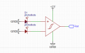
I'm am not sure if this is feasible, and how exactly to set it up without running significant currents through the photodiodes, I am thinking something similar to the attached image. Any ideas about how to implement something like this with minimal circuitry would be appreciated
When I measure the voltage across a photodiode while hitting it with light (without connecting anything to it) - it does have up to 400-500mV between its leads without an op amp, so I am wondering if it is possible to just plug two photodiodes in forward bias into a comparator, and have it generate a HIGH/LOW signal according to the comparison.
I'm am not sure if this is feasible, and how exactly to set it up without running significant currents through the photodiodes, I am thinking something similar to the attached image. Any ideas about how to implement something like this with minimal circuitry would be appreciated
Attachments
-
 13.9 KB Views: 14


