Phase Shifter Random Oscillations

Thread Starter

Vinnie90

Joined Jul 7, 2016
86
Hi guys,

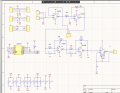
i'm building a current drive for an electromagnet. It is supposed to provide constant current amplitude up to 1kHz. The driver should also be able to provide a phase shift with respect to the input voltage. So I implemented a two stage phase shifter as described here https://pdfserv.maximintegrated.com/en/an/AN184.pdf (attacchement phase shifter).

I soldered it on the PCB I made and started testing it at 100 Hz using the amperometer as load. The main problem is that after the first stage I see random oscillations everywhere on the other stages. I thought that the issues were either on the inverting stage (U1B) left floating or with the digital potentiometer or the op amp. So I modified the circuit as in the attachments (phase shifter 2) and used instead of the LM324 an LM6144 but still no luck.

I'm a little bit lost here, so any help would be very appreciated
 

Attachments

to3metalcan

Joined Jul 20, 2014
260
So in Phase Shifter.png U1B and U1C have no resistors to ground at their + inputs. In the second file, you've removed the capacitors entirely and grounded the + inputs, which is going to make them ordinary inverting op amp stages with no ability to shift phase. Refer back to the app note you referenced and look at figure 2.
 

Thread Starter

Vinnie90

Joined Jul 7, 2016
86
So in Phase Shifter.png U1B and U1C have no resistors to ground at their + inputs. In the second file, you've removed the capacitors entirely and grounded the + inputs, which is going to make them ordinary inverting op amp stages with no ability to shift phase. Refer back to the app note you referenced and look at figure 2.
Hey,

thanks for the reply. At the non inverting input of U1B and U1C goes the digital potentiometer AD5207 to modify the phase shift (sorry in the schematic is not very clear). I removed C1 and C2 because I got weird oscillations and I wanted to check whether it was a problem with the phase shifter. But also in the normal inverting configuration I see this noise oscillations overlapped to my input sine.
 

Audioguru

Joined Dec 20, 2007
11,248
The LM324 and lM6144 have a fairly high noise output since they are not made for low noise audio.
Your circuit will oscillate or pickup mains hum and other interference if it is built with wires all over the place (antennas for interference) on a breadboard.
 

Thread Starter

Vinnie90

Joined Jul 7, 2016
86
The LM324 and lM6144 have a fairly high noise output since they are not made for low noise audio.
Your circuit will oscillate or pickup mains hum and other interference if it is built with wires all over the place (antennas for interference) on a breadboard.
I have the circuit on a PCB, only hanging wires are the ones for probing. Maybe I'll post a picture of how these oscillations look like
 

to3metalcan

Joined Jul 20, 2014
260
I have the circuit on a PCB, only hanging wires are the ones for probing. Maybe I'll post a picture of how these oscillations look like
I'm afraid this schematic is really unhelpful! What is U3? Is it okay that with the ammeter as a load it's going to be running at 100% negative feedback? Many power devices will oscillate (and can easily drive those oscillations into other devices via large input currents or the power supply rails) in that configuration. What is the resistor you're using in the feedback network, there? What are the values of the bypass caps? Have you tried running the op amp portion of the circuit without U3 to see if it's actually what's causing the problem?
 

Thread Starter

Vinnie90

Joined Jul 7, 2016
86
I'm afraid this schematic is really unhelpful! What is U3? Is it okay that with the ammeter as a load it's going to be running at 100% negative feedback? Many power devices will oscillate (and can easily drive those oscillations into other devices via large input currents or the power supply rails) in that configuration. What is the resistor you're using in the feedback network, there? What are the values of the bypass caps? Have you tried running the op amp portion of the circuit without U3 to see if it's actually what's causing the problem?
The ammeter was the actual problem....tried to run the circuit with the ammeter in series with an electromagnet and everything worked very smoothly!!! I don't understand though why a load that should have very low reactance should not properly work. In the datasheet they usually specify the maximum reactance for an inductive load....could you guys please clarify that?

Thanks :D
 

to3metalcan

Joined Jul 20, 2014
260
The ammeter was the actual problem....tried to run the circuit with the ammeter in series with an electromagnet and everything worked very smoothly!!! I don't understand though why a load that should have very low reactance should not properly work. In the datasheet they usually specify the maximum reactance for an inductive load....could you guys please clarify that?

Thanks :D
Sans any other info, I would guess that the ammeter presents such a low impedance (reactive or otherwise) that your driver IC (whatever it might be) is getting too much negative feedback and becoming unstable. When you add the magnet coil, its impedance reduces the negative feedback by forming a voltage divider with R1 and causes the device to run at a gain where it is stable.
 
Top