Facebook
 Google
 GitHub
 Linkedin
Hi Guys....
I am in need of a sinewave oscillator for playing and experimenting with transistors and small signal amplifiers
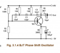
so I thought i'd use a phase shift oscillator since I don't need to vary the frequency, just a stable 1Khz signal is all I
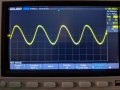
need, I built the circuit that I found online and have included which gives me 578 Hz or near as damn it, thing is
the distortion shows up really good and I would like something more pure, where is the first place to go to try
to correct this distortion?....i'm not looking for perfection 100% but surely a better result is achievable somehow?
I am in need of a sinewave oscillator for playing and experimenting with transistors and small signal amplifiers
so I thought i'd use a phase shift oscillator since I don't need to vary the frequency, just a stable 1Khz signal is all I
need, I built the circuit that I found online and have included which gives me 578 Hz or near as damn it, thing is
the distortion shows up really good and I would like something more pure, where is the first place to go to try
to correct this distortion?....i'm not looking for perfection 100% but surely a better result is achievable somehow?
Last edited: