PELKO ELECTRIC MICROFURNACE MF2207-D5A

Thread Starter

matteomarini

Joined Dec 2, 2023
35
Hi to everyone

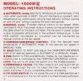
I am trying to fix one old space heater from PELKO, the microfurnace. These were great devices allowing to go from 350W up to 1500W, super silent and quite effective. I have two of the but unfortunately model are different and I cannot compare.

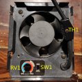
The system has 3 functions: heating (automatic or manual) and fan (no heating at all). One switch is used to select the heating / fan, one potentiometer to set the temperature (and fan speed) and one switch for manual/auto mode. In auto mode a temperature sensor communicates with the controller for feed-back.

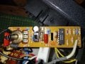
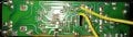
The issue is that the heater runs all the time at full speed and full heat, no control is possible. I took it apart and discovered that one part of the PCB copper trace is broken. I tried to fix this and discovered another broken trace. In addition, i fear that some of the detached and broken traces created some short somewhere.

I found a similar thread related to a closely resembling ceratech product. As finding the schematic is almost impossible, I have started reverse engineering the PCB with the aim of understanding how to check everything. The controller uses the ubiquitous LM324N and a MAC97A6 triac. Some of the diodes are unreadable and one of the components is unknown to me (the black horizontally mounted).

Q1: Does anybody have a schematic of a generic space heater to get some sort of inspiration with regard to its working ?
Q2: Do you believe I can detach the fan and heating element to test the controller or shall it be connected at all the times ?

Any help is appreciated.
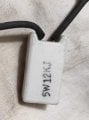
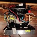
pcb-top.jpgpcb-bottom.jpgpcb.png
 

Irving

Joined Jan 30, 2016
5,039
Did you actually create the schematic or are you expecting someone to do it for you?

Do you know what caused the loss of the traces? Overload, a short, or ??? There doesn't appear to be any burning of the PCB there..

The black diode, top right is one of the 1N400x series, probably a 6 or 7, the others (marked ZD1, ZD2) are zener diodes of the 1N52xx series, while the 2 near the LM324 maybe zeners or just small signal diodes eg 1N4148.

The 'black horizontal thing' top left is probably an inductor, it should read low ohms continuity.

What does the switch in the middle of the board do? Where is the other switch connected?

There appears to be three wire connections to the board, 2 on the left, top & bottom, and one on the right - where do they go?
 

Thread Starter

matteomarini

Joined Dec 2, 2023
35
Hi Irving
very kind to get your views !

Q=your question
F=your finding
A=my answer

(Q1) Did you actually create the schematic or are you expecting someone to do it for you?
(A1) I am creating the schematics : i quickly learned KICAD for this and, after working out the images with GIMP (graphical application), I am ready to move on

(Q2) Do you know what caused the loss of the traces? Overload, a short, or ??? There doesn't appear to be any burning of the PCB there..
(A2) No clue, however you're right, no burning at all around the PCB

(F1) The black diode, top right is one of the 1N400x series, probably a 6 or 7, the others (marked ZD1, ZD2) are zener diodes of the 1N52xx series, while the 2 near the LM324 maybe zeners or just small signal diodes eg 1N4148.
(AF1) Will try to remove and read exactly what they are.

(F2) The 'black horizontal thing' top left is probably an inductor, it should read low ohms continuity.
(AF2) After studying it a bit, I noticed it is connected to the TRIAC : is this probably an optoisolator for activating the TRIAC gate ?

(Q3) What does the switch in the middle of the board do? Where is the other switch connected?
(A3) The switch selects MANUAL / AUTO mode

(Q4) There appears to be three wire connections to the board, 2 on the left, top & bottom, and one on the right - where do they go?
(A4) Eagle-Eye :) on the top PCB you have: GND, FAN and PR. PR is connected to a large ceramic resistor (see picture). On the bottom of the PCB you have the two connections to the thermostat resistor
 

Attachments

Irving

Joined Jan 30, 2016
5,039
How's the schematic coming along?

How is the heating element connected with the board?

Where does the other side of the ceramic resistor connect to?
 

Thread Starter

matteomarini

Joined Dec 2, 2023
35
How's the schematic coming along?

How is the heating element connected with the board?

Where does the other side of the ceramic resistor connect to?
Q1) Am working on it : started documenting the components outside of the controller: fan, heater, switch, resistor etc

Q2) One connection from the main through a thermostat: the other one through the controller (will send you the scheme)

Q3) It's connected to the PR pin (first picture, top right, flipped)

Looks as a simple controller, however grasping it requires some effort :)
 

Thread Starter

matteomarini

Joined Dec 2, 2023
35
Q1) Am working on it : started documenting the components outside of the controller: fan, heater, switch, resistor etc

Q2) One connection from the main through a thermostat: the other one through the controller (will send you the scheme)

Q3) It's connected to the PR pin (first picture, top right, flipped)

Looks as a simple controller, however grasping it requires some effort :)
Here what's around the controller
 

Attachments

Thread Starter

matteomarini

Joined Dec 2, 2023
35
Here what's around the controller
How's the schematic coming along?

How is the heating element connected with the board?

Where does the other side of the ceramic resistor connect to?
Hi Irving, still working hard on the schematics : I went back to libreoffice draw for getting a better view. Doing it with paper and stencil would have been a better situation if I count the wasted time :) ..

Perseverance is driving me: will come back as soon as I am ready !
 

Thread Starter

matteomarini

Joined Dec 2, 2023
35
I finally almost-finished the circuit schema : a lot of work for such a simple circuit ! I will try to understand it ... it does not look good so far. I thought that KICAD had some sort of tool for auto-arranging for pretty printing. No way.
 

Attachments

Irving

Joined Jan 30, 2016
5,039
Hmmm, not sure your schematic is 100% correct. Here's my take on it..., though I don't have all the switches etc. The circuit is one of many ways to do a phase-shift speed control of the fan.

The external ceramic resistor R16 drops mains voltage (110 or 240?) at PR down to around 30v, rectified by D2 and smoothed/stabilised by C2 & ZD1 to give a positive supply rail of approx 30v DC. A sample of the AC voltage at PR is taken by R1 and fed to both U1C and U1D which together act as a zero crossing detector - the output of U1C drops to zero volts for approx 300us every time the AC input crosses through zero volts. This discharges C3 which then charges back up via R7 and R17 giving a pseudo-triangular wave at the +input of U1B. The other input of U1B is a voltage either created by U1A and the thermistor (SW1 up) or fixed by VR1 (SW1 down). When the ramp voltage exceeds the set volts the output of U1B goes to approx 30v triggering the triac and allowing current to flow through the fan, thus VR1 and/or the thermistor controls the fan speed. The simulation below shows an example...

Now we know how it works we can attempt a fix.... but that's for another post...

1702320058721.png

1702322509188.png
 
Last edited:

Thread Starter

matteomarini

Joined Dec 2, 2023
35
Hmmm, not sure your schematic is 100% correct. Here's my take on it..., though I don't have all the switches etc. The circuit is one of many ways to do a phase-shift speed control of the fan.
....
Irving, I am quite impressed by what you have done and your explanation. I will now study it in great detail. Th overall control function is indeed to steer the fan speed.

To complete the information I enclose two pictures where you see TH1, SW1 and the rotary selector and the instruction page of a similar model.

Basically you have 2 selector's positions (beside OFF)

(a) FAN+HEAT : in this position the heater is ON and you can choose (SW1) manual or automatic mode of operation. In automatic mode the temperature is set via RV1 and sensed via TH1 to control the speed of the fan (i guess no heat control since the heater it is not connected to the controller). In manual mode, you control the temperature via RV1 and this is also setting the fan spped.

(b) FAN ONLY : no neater, fan only

In the meantime I tried to fix the broken wiring : net result is that the FAN does not turn on anymore.
 

Attachments

Irving

Joined Jan 30, 2016
5,039
Fixing the controller...

Obviously you need to replace the missing tracks - be careful with the broken 'ground' (black line in image below) that it doesn't touch the pad above it, if you are using bare copper. The red line is the +30v rail, unfortunately the voltage stabilising diode ZD1 is at the end of that run so the broken track means the voltage at the + input of the LM324 (pin4) will have risen to around 80 - 100v so it is highly likely that the LM324 is dead and it probably didn't do the electrolytic capacitor (yellow circle) much good either.. What exactly failed isn't clear. but close inspection of the tracks around that ground trace suggests a flashover? Maybe the track got hot and some creepage occurred. Another possibility is that the electrolytic capacitor went short, or ZD1 failed.

Where we go from here depends on what test equipment you have available. I have to give the obligatory warning that you are dealing with mains voltages here so testing on live power is inherently dangerous.

1702390846567.png
 

Thread Starter

matteomarini

Joined Dec 2, 2023
35
Fixing the controller...

Obviously you need to replace the missing tracks - be careful with the broken 'ground' (black line in image below) that it doesn't touch the pad above it, if you are using bare copper. The red line is the +30v rail, unfortunately the voltage stabilising diode ZD1 is at the end of that run so the broken track means the voltage at the + input of the LM324 (pin4) will have risen to around 80 - 100v so it is highly likely that the LM324 is dead and it probably didn't do the electrolytic capacitor (yellow circle) much good either.. What exactly failed isn't clear. but close inspection of the tracks around that ground trace suggests a flashover? Maybe the track got hot and some creepage occurred. Another possibility is that the electrolytic capacitor went short, or ZD1 failed.

Where we go from here depends on what test equipment you have available. I have to give the obligatory warning that you are dealing with mains voltages here so testing on live power is inherently dangerous.

View attachment 309847
Many thanks for your brilliant analysis. I personally have no clue about what happened. The only fact I know is that in the current state the heater and fan were on and working at full power. The fact that I only found a small portion of the track is also strange. It could also well be that the previous owner attempted a repair although the heater looked pristine.

My equipment at this moment is quite poor, just a multimeter: my oscilloscope is not available at this time. I have in the meantime placed an order for the LM324N.

What I could do now

a) fix the broken tracks
b) Detach and check ZD1 and the condenser
b) reconnect the controller and measure tension on LM324N (pin4 and pin11) for ascertaining it is in the 30V range (or less but no more)

What else could I quickly check ?
 

Irving

Joined Jan 30, 2016
5,039
That's pretty much all you can do..

1. Disconnect PCB & fix tracks.
2. With multimeter on ohms range check resistance between +30v rail (red lead) and ground (black). Should be low then increasing if electrolytic cap is OK. If permanently low remove LM324 - use low-melt solder and wick to avoid damaging tracks. If still low remove cap and/or ZD1.
3: Check 1N4004 diode using multimeter on diode range - should be approx 0.6v volts one way round and open circuit the other.

Don't attempt to power it up for now.
 

Thread Starter

matteomarini

Joined Dec 2, 2023
35
That's pretty much all you can do..

1. Disconnect PCB & fix tracks.
2. With multimeter on ohms range check resistance between +30v rail (red lead) and ground (black). Should be low then increasing if electrolytic cap is OK. If permanently low remove LM324 - use low-melt solder and wick to avoid damaging tracks. If still low remove cap and/or ZD1.
3: Check 1N4004 diode using multimeter on diode range - should be approx 0.6v volts one way round and open circuit the other.

Don't attempt to power it up for now.
Will do that ...
 

Thread Starter

matteomarini

Joined Dec 2, 2023
35
Will do that ...
Here what I have done so far:

- Tracks fixed

- The measure between the +30V rail and ground was permanently low.

- I disconnected the diode for a check and it is ok (my meter set to diode reported 645 and 0 as expected)

- I removed the condenser and I discovered it is dead: charging it with 12V DC had no results. I charged a new one to make sure it is fit and, once verified it is now in place

- I am waiting for the shipment of the new LM324 and the desoldering kit to proceed further

I cross my fingers and the fact to discover that the cond is dead confirms your diagnosis. Is there a test (sufficient or necessary or both) to check that the LM324 is dead as well (for curiosity)?
1702547139144.png
1702547212346.png
 

Irving

Joined Jan 30, 2016
5,039
The zener sounds like its ok, but if you have a power supply > 32v you could check the zener breakdown voltage. Wire the zener in series with a 10k resistor, the bar on the zener pointing towards the resistor and the supply +, then check the voltage across the zener; I'd expect 24 - 30v. If its same as the power supply then its probably damaged..
 
Top