PCB sizing for 25A-30A

Thread Starter

ArakelTheDragon

Joined Nov 18, 2016
1,362
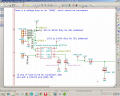
I need to pass 25A through the PCB, in order to use a SOICN 8 hall sensor to measure the current through a battery pack of 24V, 25A. I will make the trace for 30A.

1. According to the online calculators I need a 16.4mm top copper or bottom coppr trace and a 43mm internal layer trace, are the mm ok?
2. Which layer is prefered (I guess top)?
3. What will happen is I connect 3 traces of 5.5mm each instead (looks like a good option to me)?
 

ericgibbs

Joined Jan 29, 2010
18,872
hi,
The other point you need to consider is the copper weight/ft sqr. [ 0.5oz thru 3 oz]
Look at this link.
https://www.google.co.uk/url?sa=t&rct=j&q=&esrc=s&source=web&cd=1&cad=rja&uact=8&ved=0ahUKEwj8y-_mpLnaAhWOWsAKHesCBdkQFggnMAA&url=http://www.4pcb.com/trace-width-calculator.html&usg=AOvVaw1DlLVZH-a3Yt5pahI-Z8io

Clip:
The original graphs that this tool is based on (published in IPC-2221) only cover up to 35 Amps, up to 0.4 inches of trace width, from 10 to 100 degrees C of temperature rise, and copper of 0.5 to 3 ounces per square foot.

E
 

kubeek

Joined Sep 20, 2005
5,795
I recommend using saturn pcb toolkit, it calculates the temperature rise of a pcb trase, current capability of vias and much more.
 

jpanhalt

Joined Jan 18, 2008
11,087
Remember, the main limitation is temperature. If there is air flow over it or the use is intermittent, then the ratings go up considerably.
 

DickCappels

Joined Aug 21, 2008
10,187
You will save yourself a lot of grief if you use busbar (or appropriately sized solid copper wire) for most of the high current runs. You can solder solid copper wire onto the printed conductor to get the effect of a busbar.
 

Thread Starter

ArakelTheDragon

Joined Nov 18, 2016
1,362
It will be in a battery bank of 2 batteries by 2V in a metal frame. It will on top, between the battery top and the metal frame top. The battery bank will be sitting while charging and moving while the AGV is moving. I guess there can be a whole in the metal frame, for the air flow.
 

Thread Starter

ArakelTheDragon

Joined Nov 18, 2016
1,362
You will save yourself a lot of grief if you use busbar (or appropriately sized solid copper wire) for most of the high current runs. You can solder solid copper wire onto the printed conductor to get the effect of a busbar.
I was intending to do this before, but the requirements can get harder and harder. Like putting a Hall sensor to measure the current. I do not know if I can just solder wires to the hall sensor on the PCB? In this case, how big should the pads be or any other requirements? The hall sensor is Alegro ACS724 with already made pads on a SOICN 8 package.

EDIT: Plus sooner or later I will need a 30A trace, so it is good to know this.
 

DickCappels

Joined Aug 21, 2008
10,187
I would solder the hall sensor to the largest pads you can make without shorting, then bring the solid copper wire and as wide-as-you-can-make-it traces right up to the pads.
 

Thread Starter

ArakelTheDragon

Joined Nov 18, 2016
1,362

Attachments

Thread Starter

ArakelTheDragon

Joined Nov 18, 2016
1,362
I found something interesting, that I do not know if I should believe.
It gives the track width and cross section (area of the wire). Unfortunately it also states that the maximum rated current is 25A and not 30. This is for the finder 66.22 relay or 66.82. The datasheet is in the link:
https://gfinder.findernet.com/public/attachments/66/EN/S66EN.pdf

The rest is in the picture.
 

Attachments

Top