Hi E,
Yes, 18F4431 PIC. What has happened to the last 3x was both of the VDD pins start sparking, then burn out.
When cool, it starts up and flashes the LEDs, for about 1/2 min, then 'heat'
C.
I have 3x meters that will measure current, and all of them need attention, between them I got the above reading. EDIT:Just remembered an old analogue meter, that shows 100mA.
C
Hi E,
I agree, there's something strange happening, unless, I've made an error somewhere. (I hope not)
All the PIC pins show K or M Ohms.
The clock, INT 8mHz only.
Hi E,
The phone idea doesn't work, it just shows black. I also tried it on a soldering iron =same.
With the power supply instead of the REG, the same happens: The PIC starts flashing LEDS (although one has deteriated to a weak flash) After 1/2 min the bright LED starts failing, so I switched off.
NOTE: When I made PCB6 (This one) I made a timing error in the PCB printing, which left slightly mottled tracks, could this have the effect we're experiencing.
PCB7 will be necessary eventually as there are lots of changes to make, caps etc. Many components, can be reclaimed, so not too expensive, and good practice.
EDIT: I removed the 4431 LEDs and switched the power supply on. The current meter, showed fast current changes around 100mA.
C.
Hi,
I tried a couple of ideas, including removing the 18LF4620 PIC, that the offending 4431 is connected to, but same result. I think the 4431 is fried by now. Suspect me and my PCB making.
I found an abandoned PCB6, and programmed it with the LED flash program, and it flashes happily, and cool.
The current goes between 7mA and 13mA, but that seems too low, so again suspect me or my equipment, either way it is consuming a low current.
NOTE: No caps on the REG.
At £5 (18F4431 PIC) for 5 minutes of tests, it's a bit too expensive.
I will redesign the PCB (PCB7) with the above suggestions, and post it here before etching.
C.
Hi J,
I read the section in the D/S showing 300mA. Now reading a different section, see it is much less. <1mA.
NOTE: No capacitors (yet), on this abandoned PCB, and running with 10V.
Regarding PCB7: Noting the above power readings, at 10V. It would be much easier to use the same 3x REGs with the suggested CAPS, also it would be easier if the 3.3V REGs could be used straight from the eventual 12V supply, without need to go through the 5VREG. Does this seem ok. (All past PCBs have run happily with this set-up) I'll add the heat syncs to the new PCB.
C.
Also remember that the 30*30mm heatsink in the datasheet is 2oz copper, not your standard 1oz board. So you cannot run those regulators even at 150mA with only a 1oz copper board design and with 30*30mm heatsink pad.
One more note in the datasheet:
"As a result, if the device is continuously operated in an overheated condition, the output will appear to be oscillating."
Maybe consider using a higher current capacity 5V regulator to then feed the 3.3V regulators. The 5V version of the NCP1117 can't handle all that current either. A LM7805 with a small heatsink probably can.
Hi S and J,
On an earlier PCB, I noticed the 18LF4620 REG hot to the touch with almost all of the peripherals working, so I can see that what your saying is true. Ok, I'll 'up' the 5V REG and run both 3.3v REG through it.
It's a bit missleading to see 1amp output when buying these components!
An ammeter on the power line would be handy, as my calculating is not good.
Thanks.
C
Calibration doesn't have to be done all that often if you don't move the scope much. I keep my scopes on UPSs so they never suffer power-conditioning issues, and when I turn any old TDS scope on, I leave it on all day- because it's a tube-display. I also run the display intensity as low as I can reasonably tolerate, and turn it all the way down when I step away. It's a tube display, which means phospher burn in is possible, so I avoid that by what I described above.
I can't speak for the probes you referenced other than to say, for the price, if S&H is dirt-cheap- try it. They are unbranded, which means they are basically 'knockoffs' made in China- but that doesn't mean they are bad. At that price you can get one and compare it with one of your known probes and see how it behaves. If acceptable- use it. Barring having really detailed information on how it's put together so you can actually evaluate how it works- you're left with trying if it doesn't cost much. For my part, I have no problem paying $120 or less for a scope probe for my TDS360, if it's tektronix and is new. The probes are literally more impactful to your circuit than the scope- the scope only sees what the probe passes on- so probe quality is vital.
Hi B,
Noted!
Mine's an LCD screen, so a bit easier. Actuall it's not very bright, but that's ok.
The probes are spare, and I hope the end clips fit the originals, so I have two working. Also I will be able to use an external source for the trigger.
C
Hi E,
I received the probes, they look good. I'm not sure how to test probes, but I superimposed probe A over B (Tectronics and New) and with ON/OFF and 8mHz XTL, they were the same.
C.
Hi,
On the PCBs I use a Mux switch FST3253, it is powered by 5V, this is why I use a 5V REG. It is switched with the PIC 3.3V, and has been fine.
Can someone let me know that this is ok, please.
Does it need Caps?
I'm making PCB7 with all of the above suggestions, expecially regarding REG Caps. Each REG needs 2x 10uF Caps plus a 100nF. Each PIC has a 100nF as near to each VDD-VSS PINS (2x) as poss.
This would mean 3x 100nF Caps for each PIC, is this correct?
C.
Hi,
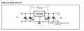
I just received some 10uF polarised Caps for PCB7, as suggested, also there are some 2A 7805 Regs. In the data sheet it shows this:
The D/S shows 0.1 and 0.33uF Caps. The 0.1uF has been mentioned in the thread, but the 0.33uF hasn't.
I have been altering the SCH where I use a 0.1uF none polarised + 10uF polarised each side of the 5V and 3.3V Regs.
Can someone clarify please.
C.
 Facebook
 Google
 GitHub
 Linkedin
")