My guess is that it is a very low value resistor being used as a current shunt to monitor the current the is either supplying or taking. (You have not told us what the board is.) I suspect it is wired in series with the 30 amp fuse.
The track connected to the left hand end of the component does not look capable of carrying 30 amps so I suspect there is a wider track on the other side of the board to carry a higher current. A picture of the other part of the component that you removed may be helpful.
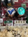
R65 looks the same on your board as it does in the picture in your link. It does not look like I would expect it to if it had overheated. Measure the resistance between the the two points where it is soldered into the board. I expect the reading to be so low that it will read the same as when the meter probes are shorted together.
I am confused by your picture in post #5. R40 seems to be missing. What makes you think that R65 is faulty ?
That makes sense now. Show us R40 that you removed and measure the resistance between the ends of it's wires that were soldered into the board. The item still remaining on the board in R40 position is probably just a spacer to keep the resistor spaced away from the board. Just because the resistors look the same it does not mean that they are the same value. After seeing the information on the board I would GUESS that R40 is in series with the feed to the 24 volt 0.5 HP motor. I suggest tracing enough of the schematic to see if my GUESS is correct. If it is then first look for a mechanical problem putting excess load on the motor.
It will be hard to measure the resistor. Maybe 0.01 ohm.
Removing the resistor is not necessary. I don't think the other parts on the board are going to cause much error.
You probably need to do a four-wire measurement.
 Facebook
 Google
 GitHub
 Linkedin