 Facebook
 Google
 GitHub
 Linkedin
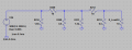
I'm working on building a passive PI step attenuator with 2 or 3 steps for audio purposes (Freq range: 0-20KHz )
i've started with just two steps and at the simulation it seems fine but in the reality - it's adifferent story
it seems like a simple voltage divider but i couldn't understand why the actual measurement are different from the simulation
i've designed each step to attenuate by ~ 29 db
the results of the circuit at the simulation are : Vin 4 V ,after one step : ~180 mV (Vmax) ,after the second step : ~8.2 mV (Vmax)
the results of the circuit that i have built are: Vin 4 V ,after one step : ~202 mV (Vmax) ,after the second step : ~26 mV (Vmax)
i'm awer to the fact that there are noises that takes place in the measurements but still with differents Vin that i've tried the attenuation of the second step seems to be very low than it should be
any ideas why or how to solve the problem ???
thanks
Attachments
-
 5.9 KB Views: 5


