Facebook
 Google
 GitHub
 Linkedin

Moderator, Please delete this message. Sorry that I had a double post, but my browser crashed when I tried to submit the first time, and I ended up making 2 posts. Don't see how I can delete this duplicate post. Thanks.
Hello, This is my first post here. I was actually searching on Google about parallel MOSFETs and some posts on this site came up. I am not very strong in my electronics understanding, so I thought I would see what some electronics experts think.
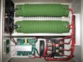
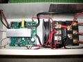
I have a wind turbine (10 ft diameter blade rotor) that is rated for 2kW and I've seen peak output up to 3.5kW on a couple occasions. The wind turbine charges a 48V battery bank. Peak amperages I've seen are around 65A from the wind turbine during very strong wind gusts. The controller has a rectifier to convert the 3 phase wild AC turbine output to DC and then a control board that dumps wind turbine power to big heating resistors when the battery is fully charged. In addition, when the wind turbine RPM is too high, the control dumps the turbine output to the resistors to slow down the turbine. Heating resistors are 4kW total. The controller I am testing uses MOSFETs to dump the power to the heating resistors. I'll attach some pictures.
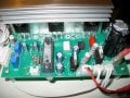
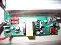
There are 3 MOSFETs attached to a heat sink. They are made by IXYS and their part number is: IXTQ82N25P . Here's the spec sheet on it.
http://ixdev.ixys.com/DataSheet/99121.pdf
It lists a maximum amperage of 82A.
I've got 3 questions for you electronics experts...
1) Does the 3 of these MOSFETs mean that they can control a maximum of 3 x 82A?
Just curious what the power capacity of these 3 MOSFETs really is in the real world.
2) Could 2 more identical MOSFETs be solderd to the board and increase the current switching capacity further, or would the rest of the circuit board not be able to drive the 2 additional MOSFETs?
That might be a dumb question, but I am not familiar enough with electronics to know. The 3 MOSFETs might be more than adequate as is as long as I keep them cool enough.
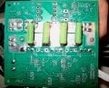
The 3 MOSFETs that are on there now appear to be screwed to the heat sink dry. No thermal paste. I think that was intentional, because the heat sink is actually used as a conductor for the dump circuit. The heat sink screws to the board over a large tinned copper trace. I've tested continuity and the heat sink is used as a conductor. I think that's why they didn't put thermal paste on there. I'm concerned that the MOSFETs will get too hot this way, but I don't want to add thermal paste and cause other problems. I thought if I added 2 more identical MOSFETs, I might increase the reliability of the system. There are spots on the board and the heat sink is drilled/tapped for 2 additional MOSFETs. Just don't know if the driver circuit could handle 2 more. This same circuit board is used for a larger wind turbine where they apparently use 5 MOSFETs. I don't know if the only difference between my board and the one in other controller is 2 less MOSFETs.
Not sure if I should even try to add 2 more MOSFETs or just try to keep the existing 3 MOSFETs as cool as possible with some better fans.
I'll attach some pictures.
Thanks for any advice,
Edward
Hello, This is my first post here. I was actually searching on Google about parallel MOSFETs and some posts on this site came up. I am not very strong in my electronics understanding, so I thought I would see what some electronics experts think.
I have a wind turbine (10 ft diameter blade rotor) that is rated for 2kW and I've seen peak output up to 3.5kW on a couple occasions. The wind turbine charges a 48V battery bank. Peak amperages I've seen are around 65A from the wind turbine during very strong wind gusts. The controller has a rectifier to convert the 3 phase wild AC turbine output to DC and then a control board that dumps wind turbine power to big heating resistors when the battery is fully charged. In addition, when the wind turbine RPM is too high, the control dumps the turbine output to the resistors to slow down the turbine. Heating resistors are 4kW total. The controller I am testing uses MOSFETs to dump the power to the heating resistors. I'll attach some pictures.
There are 3 MOSFETs attached to a heat sink. They are made by IXYS and their part number is: IXTQ82N25P . Here's the spec sheet on it.
http://ixdev.ixys.com/DataSheet/99121.pdf
It lists a maximum amperage of 82A.
I've got 3 questions for you electronics experts...
1) Does the 3 of these MOSFETs mean that they can control a maximum of 3 x 82A?
Just curious what the power capacity of these 3 MOSFETs really is in the real world.
2) Could 2 more identical MOSFETs be solderd to the board and increase the current switching capacity further, or would the rest of the circuit board not be able to drive the 2 additional MOSFETs?
That might be a dumb question, but I am not familiar enough with electronics to know. The 3 MOSFETs might be more than adequate as is as long as I keep them cool enough.
The 3 MOSFETs that are on there now appear to be screwed to the heat sink dry. No thermal paste. I think that was intentional, because the heat sink is actually used as a conductor for the dump circuit. The heat sink screws to the board over a large tinned copper trace. I've tested continuity and the heat sink is used as a conductor. I think that's why they didn't put thermal paste on there. I'm concerned that the MOSFETs will get too hot this way, but I don't want to add thermal paste and cause other problems. I thought if I added 2 more identical MOSFETs, I might increase the reliability of the system. There are spots on the board and the heat sink is drilled/tapped for 2 additional MOSFETs. Just don't know if the driver circuit could handle 2 more. This same circuit board is used for a larger wind turbine where they apparently use 5 MOSFETs. I don't know if the only difference between my board and the one in other controller is 2 less MOSFETs.
Not sure if I should even try to add 2 more MOSFETs or just try to keep the existing 3 MOSFETs as cool as possible with some better fans.
I'll attach some pictures.
Thanks for any advice,
Edward
Attachments
-
 97.9 KB Views: 133
-
 79.3 KB Views: 110
-
 57.8 KB Views: 140