Parallel connecting voltage regulators to servoes with common controller

Thread Starter

Little Boolean

Joined May 21, 2019
7
Hello

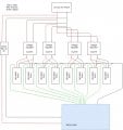
I am on my way to control eight servoes with a Arduino mega 2560. However these servos are rather large, and the voltage regulators I have for them (regular buck converter) are only capable of supplying the amps for two servos each. In other words, there are four regulators, each connected to two servos each. The supply is a lipo battery.
I want to control all the servos via pwm directly on the board. Will connecting all these as is, be safe, or could it be that the regulators could be damaged by reverse voltage from another regulator that might have a higher voltage etc.?

(Sorry if I have posted this in the wrong part of the forum)
 

danadak

Joined Mar 10, 2018
4,057
The regulators somehow must sense the current they are supplying in order
to regulate in a sharing mode. Most small buck/boost converters do not have
that capability.

What is the part number/vendor of the reg you are using ?


Regards, Dana.
 

crutschow

Joined Mar 14, 2008
34,282
there are four regulators, each connected to two servos each.
I want to control all the servos via pwm directly on the board. Will connecting all these as is, be safe, or could it be that the regulators could be damaged by reverse voltage from another regulator that might have a higher voltage etc.?
If the supplies are separately connected to power two servos each, how can there be any interaction between the supplies? :confused:
 

Thread Starter

Little Boolean

Joined May 21, 2019
7
The regulators somehow must sense the current they are supplying in order
to regulate in a sharing mode. Most small buck/boost converters do not have
that capability.

What is the part number/vendor of the reg you are using ?


Regards, Dana.
They are XL4015 based converters
 

Thread Starter

Little Boolean

Joined May 21, 2019
7
If the supplies are separately connected to power two servos each, how can there be any interaction between the supplies? :confused:
The supplies, which go to the servos are all connected to common ground. And in order to control the servos (rc ones), power, signal and ground most be connected to the board, all three for all servos
 

crutschow

Joined Mar 14, 2008
34,282
The supplies, which go to the servos are all connected to common ground. And in order to control the servos (rc ones), power, signal and ground most be connected to the board, all three for all servos
Having the grounds (and thus the signals) common is not a problem.
If you need to connect all the power supplies to the board, then isolate the supplies with Schottky diodes from each supply to the board.
The board will then see the voltage from the highest voltage supply (minus the small forward diode drop) but that shouldn't be a problem.
 

Thread Starter

Little Boolean

Joined May 21, 2019
7
Having the grounds (and thus the signals) common is not a problem.
If you need to connect all the power supplies to the board, then isolate the supplies with Schottky diodes from each supply to the board.
The board will then see the voltage from the highest voltage supply (minus the small forward diode drop) but that shouldn't be a problem.
I'am planning to to have a dedicated supply to drive the board itself. Both because I need a step up regulator to be in the range, and to eliminate noise etc that might be caused by the servos. The voltage from servo regulators into the board are only there in order for the signal to work. Will I still need the diodes, and should the dedicated supply for the board also have the diodes (considering power comes from the same battery)?
 

Thread Starter

Little Boolean

Joined May 21, 2019
7
Depends upon what the servo power is connected to in the driver board.
Can you show a schematic of the board?
Depends upon what the servo power is connected to in the driver board.
Can you show a schematic of the board?
Not sure if this schematic incorporates everything, but if need the searchword is "mega2560". There are also pinout maps for the complete board as well.

Edit: Noted how the text in the image is close to unreadable, but this link will take you to the editor it was made in, much easier to see https://easyeda.com/editor#id=cf9446799d3340098a4f0c53ddf8f31a
 

Attachments

Last edited:
Top