P channel MOSFET to disconnect a load

Thread Starter

Lagom

Joined Feb 8, 2019
41
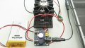
I am using Adafruit's solar battery charger and it does charge a Li-Ion battery from a solar panel as it should. It also powers an LED driver from the battery at night. The problem is that the LED driver is always powered and I want the LED to be powered only when it is dark.

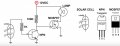
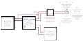
From what I read so far, it seemed that a P channel MOSFET would serve my purpose - when the gate is high (solar panel in daylight), the P channel MOSFET disconnects the load, when the gate is low (solar panel covered/at night), it connects the load.

This is not working, see attached schematic and circuit, so how should I change my set-up?

Many thanks in advance!
 

Attachments

Alec_t

Joined Sep 17, 2013
14,313
Looks like you have the P-FET back to front. The source should be at the most positive voltage and the drain should connect to the load.
 

Thread Starter

Lagom

Joined Feb 8, 2019
41
Hi, thanks; as you can see in the schematic and circuit images, the source is connected to the battery output and the drain to the load, the LED driver, and the gate is connected to the solar panel that delivers 0-7V depending on daytime.

What else may be wrong in my set-up?
 

mvas

Joined Jun 19, 2017
539
So, exactly what is wrong?
a) The LED should be ON at night <== Does this work?
b) The LED should be OFF during the day <== Does this work?

What is your "Gate to Source" voltage during the Day & Night
Is the MOSFET turning On & Off, as required?
Are all of the Black Wires at a common voltage / connection point ( "ground" ) or not?

What is the Day & Night voltage of the Solar Panel?

If you remove the MOSFET from the Charger,
and then connect the LED Driver directly to the Charger
then does the LED illuminate?
 
Last edited:

Thread Starter

Lagom

Joined Feb 8, 2019
41
Hi, thanks; the LED driver is never powered in the MOSFET set-up, neither at dusk, daytime, dawn or night (always reads around 0.1-0.2V).

G to S in full sun reads 0.1V
G to S dark hallway reads -1.8V

The MOSFET is not turning on or off, by the looks of it (I also tried with the spares I have)

The black wire of the LED is connected to the LED driver. The black wire of the LED driver is connected to LOAD on the PCB. The black wire of the battery is connected to BAT on the PCB. The black wire of the solar panel is connected to the DC jack on the PCB.

Solar panel in full sun reads 7.1V (behind PCB input jack, plugged in) or 6.7V directly at the panel's plug, unconnected
Solar panel in dark hallway reads 1.3V (behind PCB input jack, plugged in) or 0.8V directly at the panel's plug, unconnected

Without the MOSFET, the battery is charged in full sun, and the LED is permanently lit, and when the panel is covered, the battery takes over, so it all works as advertised with this solar charger PCB (as far as I can judge).

Is there more information I should provide?
 

Alec_t

Joined Sep 17, 2013
14,313
The FQP27P06 needs a Vgs of -10V to turn on fully, and an absolute minimum of -2V will get you a drain current of only 250uA, per the datasheet. So a Vgs of -1.8V won't work. You need a 'logic-level' FET with as low a Vgs(thr) as possible.
 

Thread Starter

Lagom

Joined Feb 8, 2019
41
Thanks a lot! I got these P channel MOSFETS because of a recommendation, so obviously that was wrong. I will then hunt for a P channel MOSFET as you describe it.
 

Thread Starter

Lagom

Joined Feb 8, 2019
41
Would this one be a suitable choice?

By the way, where would I find sound beginner level information on how - based on my solar panel voltage(s), battery voltage(s) and LED driver voltage - I could calculate what type of MOSFET I should buy?

From your "-10V" comment, and looking at the datasheet, I gather that with MOSFETS, I must always also look for RDS(on), right? So the one I just linked to, with -2.7V would also not be suitable in my case, correct?

Edit: When (outside) I cover the PV solar panel completely with a black hood, gate to source reads -2.3V
 
Last edited:

Alec_t

Joined Sep 17, 2013
14,313
The FET in the link might be about as good as it gets (providing your panel voltage can't exceed 20V). If you look at Fig 5 of the datasheet, Vgs = -2V allows a drain current of ~8A.
Rds(on) is always worth checking, but is particularly important for high drain current apps, since it determines how hot the FET gets.
No beginner-level reading material comes to mind. For any project, important factors to consider are working voltage, maximum current, Vgs-versus-current characteristics, power handling, package type, cooling requirements/possibilities.
 

djsfantasi

Joined Apr 11, 2010
9,162
It’s not unusual to drive your MOSFET with a logic level MOSFET, so you don’t need as much voltage from the signal in order to switch the load.

It looks like this. A logic level n channel MOSFET switches the gate of your p-channel MOSFET. A pull up resistor tobthe higher voltage is connected between the voltage source and the drain-gate connection between the two MOSFETs.
 

Thread Starter

Lagom

Joined Feb 8, 2019
41
The FET in the link might be about as good as it gets (providing your panel voltage can't exceed 20V). If you look at Fig 5 of the datasheet, Vgs = -2V allows a drain current of ~8A.
Rds(on) is always worth checking, but is particularly important for high drain current apps, since it determines how hot the FET gets.
No beginner-level reading material comes to mind. For any project, important factors to consider are working voltage, maximum current, Vgs-versus-current characteristics, power handling, package type, cooling requirements/possibilities.
My PV solar panels spike at around 7V. The high-power LED driver at its brightest setting draws 1050mA at 2.95V.
 

Thread Starter

Lagom

Joined Feb 8, 2019
41
It’s not unusual to drive your MOSFET with a logic level MOSFET, so you don’t need as much voltage from the signal in order to switch the load.

It looks like this. A logic level n channel MOSFET switches the gate of your p-channel MOSFET. A pull up resistor tobthe higher voltage is connected between the voltage source and the drain-gate connection between the two MOSFETs.
Ok, I will buy a logic level P channel MOSFET like this one here which gives RDS(on) with -2.5V/-2.7V and then see how it goes.
 

Thread Starter

Lagom

Joined Feb 8, 2019
41
You could also use an NPN BJT to control the P-MOSFET.
That sounds interesting! I found a set-up, see image below, that did that, but with an N channel MOSFET and different PV solar panel and battery voltages. Maybe I can re-configure my circuit somehow with an NPN transistor to do what was done there?
 

Attachments

Thread Starter

Lagom

Joined Feb 8, 2019
41
Ok, this is interesting. Since bright afternoon sun, I left the set-up alone until returning when natural darkness had already sat in. Measuring the voltages, I can now compare these two real-day sets:

Mid afternoon (LED is off)

6.78V PV solar panel plug
6.68V PV solar panel DC jack mount
4.19V BATT
6.49V LOAD (same reading as in original Adafruit configuration with no load connected)
0.02V LED driver
0.00V LED
-0.18V Gate-Source

Very late evening (LED slowly pulses (driver has low voltage feature in firmware I cannot disable))

0.08V PV solar panel plug
0.14V PV solar panel DC jack mount
4.19V BATT (LED pulsing slowly has not yet depleted battery measurably)
4.18V LOAD
4.10V LED driver
2.41V LED (a bit under-volted, hence the pulsing by way of the driver's firmware)
-3.9V Gate-Source

So, even so the P channel MOSFET is not the right type, at least it seems to "sort of" work. In daylight, the load is disconnected. At night, the load is connected. Just not fully.

So that means that indeed I need to wait for that P channel MOSFET with a fairly much lower RDS(on) - or I could try adding an NPN transistor as suggested above... Am I drawing the right conclusions from the measurements? Or is there something else I am missing?

Also, should there be a pull-up resistor between Gate-Source?
 

Thread Starter

Lagom

Joined Feb 8, 2019
41
Phew, that looks daunting!

I had hoped buying that lower RDS(on) MOSFET would solve my problem, now that I can see that the current P channel MOSFET "almost" works. I would have thought that Adafruit's PCB takes care of battery protection?

How about that other circuit I found that I attached above, the one with NPN transistor, would that also damage the battery?
 

crutschow

Joined Mar 14, 2008
34,416
Sorry, Looks like I lost track of the problem, so scratch post #16.
I was thinking you were protecting the battery, but you just want is to control the LED so it's on when the solar panel voltage is low.

I think the circuit below should work for you.
The LTspice simulation shows the P-MOSFET turning on the LED circuit (blue trace) when the solar panel voltage (yellow trace) drops to about 1.5V.

upload_2019-6-11_16-38-57.png
 

Thread Starter

Lagom

Joined Feb 8, 2019
41
Allright, I was worried there for a bit, since I must use the Adafruit PV solar battery chargers (I bought lots of them, one for each tree, where these set-ups will end high up).

So what you mean is to replace my FQP27P06 with that AO6407? Four drain contacts... that is just for convenience, I guess. That part is not available from Farnell, Mouser or Digikey here in Sweden, but apparently from Alibaba and similar Chinese vendors, with around 3-4 weeks shipping time. But if this low RDS(on) AO6407 IC does the trick, why not!
 
Top