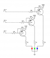
P channel MOSFET or 2N3906 PNP project

ElectricSpidey

Joined Dec 2, 2017
3,347
Keep it simple, do your tests without the controller and the transistors.

Just tie the cathode to negative thru a 1k resistor and tie the anodes directly to positive in various combinations.
 

Thread Starter

Tonyr1084

Joined Sep 24, 2015
9,744
Keep it simple, do your tests without the controller and the transistors.

Just tie the cathode to negative thru a 1k resistor and tie the anodes directly to positive in various combinations.
That is my plan. However, this morning has been fraught with internet connectivity issues. For some reason Quantum could not find any problems but there was no connection. Then there was connection for five minutes then a loss of connection. Then it happened again for 5 min's, then nothing. A technician is coming tomorrow. Meanwhile for no reason I can figure, all things are working properly. For the time being.

So since I can't get any real work done in the shop I'll go down stairs into the lab and do that exact test and report. Be back in 10 to 20 minutes with results. Maybe sooner, provided I don't lose internet connectivity again.
 

Thread Starter

Tonyr1084

Joined Sep 24, 2015
9,744
OK, as you suspected, the red cancels out all other colors. So yes, I'm going to need resistors for each individual color. And the test was performed with a single power supply and all anodes tested one by one, two by two and all three. Since the Vf of the blue and green are nearly identical they both lit on the single resistor. But when the red was added into circuit blue and green extinguished.

And my internet is still active.
 

dl324

Joined Mar 30, 2015
18,445
the red cancels out all other colors. So yes, I'm going to need resistors for each individual color.
The difference between the forward voltages of red and green/blue is about a diode drop. You could put a signal diode in series with the red led to see if that equalizes them enough.
 

Jon Chandler

Joined Jun 12, 2008
1,629
The difference between the forward voltages of red and green/blue is about a diode drop. You could put a signal diode in series with the red led to see if that equalizes them enough.
Or just do it properly with individual resistors, which will allow you to equalize light levels between the colors.
 

ElectricSpidey

Joined Dec 2, 2017
3,347
The difference between the forward voltages of red and green/blue is about a diode drop. You could put a signal diode in series with the red led to see if that equalizes them enough.
You can do that, but you still have the issue of the current dividing across 3 LED's if they are all lit.

Tony's reasoning that 3 LEDs will produce 28mA is faulty.

With a 1k resistor on the cathode you will see about 10mA on a single LED but that will be divided up when more than one is lit.

So, if divided equally when all three are lit the current would be 3.3mA each. (aprox)

Then there is also the issue of equalizing the brightness to get the best color blends. You would do this by choosing different resistors for each color.
 

dl324

Joined Mar 30, 2015
18,445
You can do that, but you still have the issue of the current dividing across 3 LED's if they are all lit.

Tony's reasoning that 3 LEDs will produce 28mA is faulty.

With a 1k resistor on the cathode you will see about 10mA on a single LED but that will be divided up when more than one is lit.

So, if divided equally when all three are lit the current would be 3.3mA each. (aprox)

Then there is also the issue of equalizing the brightness to get the best color blends. You would do this by choosing different resistors for each color.
I don't think any of your arguments matter. This is something to entertain his grandchildren. Brightness matching, dimming, etc., probably won't matter.
I would like to use them just as a hobby curiosity to show the grand children.
I remember him saying he wanted about 10mA through the LEDs, but don't recall him ever saying that he wanted 30mA through the resistor if all 3 LEDs were on.
The Vf's are (red) 2.1, (green) 2.8 and (blue) 2.9. Using a common resistor will make little difference in the brightness, so I'm not worried about that so much. Target current is around 10mA. I'm not locked into any current levels so feel free to make suggestions on that aspect as well.
 

Thread Starter

Tonyr1084

Joined Sep 24, 2015
9,744
Then there is also the issue of equalizing the brightness to get the best color blends. You would do this by choosing different resistors for each color.
Hard to tell, but they all appear to be of equal brightness. I MIGHT put a 10K in parallel to the 1K on the red line (R-total = 909.1Ω) since the other two are seeing about 9mA each. With the red at about 11mA it should be satisfactory.
This is something to entertain his grandchildren. Brightness matching, dimming, etc., probably won't matter.
So true. Doesn't matter at all. Simply stated, this is a toy to entertain my grandchildren. Let them play with the remote. Make the lights dim from one color to the next with an infinitely variable color selection. It can be made to flash wildly like a disco tech or can transition from one color to the next smoothly and gently. Brightness can be changed by adjusting the PWM in the controller. It's just a toy. Probably one that will be played with once or twice then put away to be forever forgotten until some alien race discovers planet earth and dig up the remains of an extinct human race that made such useless toys.
 

Thread Starter

Tonyr1084

Joined Sep 24, 2015
9,744
Fine do whatever you want, I will try to remember not to try and teach you anything.
I wouldn't say that I don't want to learn anything. I'm just not interested in building a Mac Truck just to move a can of peas six inches.

I do appreciate the lessons to be learned here. Just that this is not a case of necessary complexity. It's just another one of those silly notions I want to make something useful out of something I have laying around. Lots of diodes, lots of resistors, lots of transistors and some MOSFET's. Why not play with them?! The crux of my question is which is better, MOSFET's or BJT's? I got more than I asked for. Thank you all.

Back in high school for a science project I wanted to take three colored flood lights and power them through dimmers. House them in a box to shield the viewers from seeing which lamps were lit, but rather interpret the color on a screen based on which lights were lit and at what intensity. That never got made, but it was a passing thought. Since I have these materials at hand and, until now, have time to tinker with it. Just a tinker's gadget. A do nothing serious machine. Just because I can.
 
Top