Hi all,
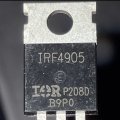
I'm testing a few P-Channel Mosfets (IRF4905) I bought.
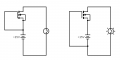
It's just the most basic setup - see sketch; battery is 15V, Incandescent light is pulling about 1.5A.
When the gate is connected to (-), the light goes on and the Mosfet reaches +60deg C. in about a dozen or so second.
Rated RDS(on) for this mosfet os 0.02Ohm.
If I understood correctly, the heat coming from that Mosfet should be 1.5 * 1.5 * 0.02 = 0.045Watts.
That wattage shouldn't be enough for the mosfet to reach this temperature so fast.
Am I doing / seeing something wrong? Or did Aliexpress sent me different speced Mosfets?
thanks for you insights!
shiny
I'm testing a few P-Channel Mosfets (IRF4905) I bought.
It's just the most basic setup - see sketch; battery is 15V, Incandescent light is pulling about 1.5A.
When the gate is connected to (-), the light goes on and the Mosfet reaches +60deg C. in about a dozen or so second.
Rated RDS(on) for this mosfet os 0.02Ohm.
If I understood correctly, the heat coming from that Mosfet should be 1.5 * 1.5 * 0.02 = 0.045Watts.
That wattage shouldn't be enough for the mosfet to reach this temperature so fast.
Am I doing / seeing something wrong? Or did Aliexpress sent me different speced Mosfets?
thanks for you insights!
shiny
Attachments
-
 3.6 KB Views: 67