Facebook
 Google
 GitHub
 Linkedin
Hello all,
I'll preface that I'm a newb when it comes to electronics, I only know what I want to achieve but don't know how to design my own circuits. I have found an overvolatge protection circuit that works, but only on low amp devices like leds.
I want to make a dummy battery for a camera.
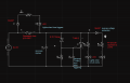
As a main power source I intend on using a phone charger 5V/2A (this could also be a power bank or a PC via USB), connected to MT3608 and I will set the output voltage to 8.3V as that is what the camera battery outputs.
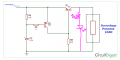
After that I want to have a protection circuit just to be doubly shure the camera doesn't get fried. So the voltage is limited with a zener diode (I'll be using a 7.5V one as the 8.2V could go as high as 8.8V before the circuit reduced the voltage, and I don't know if cameras can take that high of a voltage).
The added LED in the circuit is lit when the voltage is in the operating range that I want. And I could also add a switch so the LED and the circuit turns off when the camera is not in use but still connected to a main power source.
The problem is low amperage at the output as the camera doesn't turn on. With my limited knowledge, I think the issue is/are transistors. I didn't use BC557 as I don't have it, but I replaced it with 2n3906 which should be an equivalent. Looking at the data sheet it seem the collector current is too low for my needs? So I',m thinking I need a transistor with a higher collector current?
I don't have any high amp transistors in my basic transistor kit, so I was looking at TIP42C or something along those lines. Would I be able to just put that in for the Q1 transistor to get the result that I want (would I make a disaster?), or is there a transistor that is better suited for the job that I haven't found yet?
If not, would I have to do something like Darlington/Sziklai pair? In that case I have no clue where and what I would have to replace and add as I just found out about these two transistor configurations.
Also on a side note, I saw some mentions that the zener diode should be swapped with R4 (based on the provided image) as the circuit is otherwise faulty somehow?
I'll preface that I'm a newb when it comes to electronics, I only know what I want to achieve but don't know how to design my own circuits. I have found an overvolatge protection circuit that works, but only on low amp devices like leds.
I want to make a dummy battery for a camera.
As a main power source I intend on using a phone charger 5V/2A (this could also be a power bank or a PC via USB), connected to MT3608 and I will set the output voltage to 8.3V as that is what the camera battery outputs.
After that I want to have a protection circuit just to be doubly shure the camera doesn't get fried. So the voltage is limited with a zener diode (I'll be using a 7.5V one as the 8.2V could go as high as 8.8V before the circuit reduced the voltage, and I don't know if cameras can take that high of a voltage).
The added LED in the circuit is lit when the voltage is in the operating range that I want. And I could also add a switch so the LED and the circuit turns off when the camera is not in use but still connected to a main power source.
The problem is low amperage at the output as the camera doesn't turn on. With my limited knowledge, I think the issue is/are transistors. I didn't use BC557 as I don't have it, but I replaced it with 2n3906 which should be an equivalent. Looking at the data sheet it seem the collector current is too low for my needs? So I',m thinking I need a transistor with a higher collector current?
I don't have any high amp transistors in my basic transistor kit, so I was looking at TIP42C or something along those lines. Would I be able to just put that in for the Q1 transistor to get the result that I want (would I make a disaster?), or is there a transistor that is better suited for the job that I haven't found yet?
If not, would I have to do something like Darlington/Sziklai pair? In that case I have no clue where and what I would have to replace and add as I just found out about these two transistor configurations.
Also on a side note, I saw some mentions that the zener diode should be swapped with R4 (based on the provided image) as the circuit is otherwise faulty somehow?
Attachments
-
 34.9 KB Views: 17