Oscilloscopes Discontinuity Noise Advice

Thread Starter

dreimund

Joined Jun 6, 2018
16
Hello,

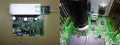
We currently run shock and vibration testing to specific standards on electrical connectors (Dsub, Rectangular, Circular). Our requirement is that we send 5volts @ 100ma and monitor for discontinuity lasting 1microsecond or longer. We use a keithley 2231A-30-3 and Tektronics DPO2002B. They are both plugged in to an isolation transformer (recommended previously). We have since switched buildings and are experiencing noise on our accelerometers (resolved low noise cable) and oscilloscopes (unresolved). Really trying to get a consultant in to evaluate everything but I can only do so what I am allowed.

In the same room running the Amplifier PAS106 when the system powers on there is no noticeable noise being picked up. When the gain on the amplifier is turned up the waveforms pickup by several magnitudes on the oscilloscopes.
upload_2018-6-6_9-49-47.png

upload_2018-6-6_9-51-3.png
The two main things I am really needing help with are:

1) It has been suggested that we switch to a shielded twisted pair wire for our electrical hookups. If we chose this option I am unsure of a few things. Would it be best to ground the shield on one side and leave it open or connect both sides? With the isolation transformer in play would grounding to the chassis of the power supply even work? Would it be smarter to not float the d/c power supply and ground the shield to the chassis?

2) Is there any one piece of equipment that would meet our requirements? Be able to send 5VDC @ 100ma and monitor for Discontinuity for 1microsecond or longer? I currently have the most experience on this system and am leaving at the end of the month. I would like to get the process as pain free as possible and if I could avoid teaching everyone our current setup would be ideal.

Thank you for any assistance or advice you can provide. I have spent countless hours(days total) searching this subject and am unable to find a for sure answer. Everything from ground the shield on one side to both sides to not at all.
 

crutschow

Joined Mar 14, 2008
34,285
1) It has been suggested that we switch to a shielded twisted pair wire for our electrical hookups. If we chose this option I am unsure of a few things. Would it be best to ground the shield on one side and leave it open or connect both sides?
The shield should be connected at one end to a good earth ground.
Where they did vibration testing at my work, they had a rod driven into the ground with salt water around the rod to provide a solid earth ground.
 

Thread Starter

dreimund

Joined Jun 6, 2018
16
I am unsure exactly what you are meaning. Without the filters on the Oscilloscope being used the noise can hit close to 4V. The DC power supply sends 5V @ 100ma through a 50ohm resistor. When there is continuity this shows up on the oscilloscope the value is very small. When discontinuity occurs with the resistor in place the oscilloscope will pick up the voltage spiking up.

Accelerometer Noise can be seen here. This was resolved with the low noise cables.Random Noise Sentek CH2.jpg

This would be the settings we use to monitor for discontinuity. Noise filter on oscilloscope has to be used see below
O-Scope Setups.PNG

S&V Running Probe Attached, 1.0V division.jpg
5.0v @ .100A Noise S&V.jpg
 

Thread Starter

dreimund

Joined Jun 6, 2018
16
Thank you! I appreciate the responses and will talk to facilities about the earth ground rod as a more permanent fix. Would there be any other suggestions in the short term for grounding one side of the shielded cable while the earth ground rod is looked into?

Is there any piece of equipment that you can think of that would meet the requirements below?
2) Able to send 5VDC @ 100ma and monitor for Discontinuity for 1microsecond or longer? I currently have the most experience on this system and am leaving at the end of the month. I would like to get the process as pain free as possible and if I could avoid teaching everyone our current setup would be ideal.
 

Thread Starter

dreimund

Joined Jun 6, 2018
16
Well 2 years of trying to solve our noise issue and I finally am able to say I have. The shielded cable did not do anything. There might of been a 20% reduction in amplitude but overall not what we were hoping to see. The issue was our 50ohm resistors in the circuit. Remove those and the signal is clean.
 

ebeowulf17

Joined Aug 12, 2014
3,307
Well 2 years of trying to solve our noise issue and I finally am able to say I have. The shielded cable did not do anything. There might of been a 20% reduction in amplitude but overall not what we were hoping to see. The issue was our 50ohm resistors in the circuit. Remove those and the signal is clean.
I thought the resistors were limiting your current to the desired 100mA. What limits current now if you've removed them?
 

Thread Starter

dreimund

Joined Jun 6, 2018
16
Our Keithley Power Supply pushes 100mA @ 0.1V-1.0V and have it set at a limit of 5V. Discontinuity there is still the jump in amplitude. There is not a defined spike rather the whole line moves up out of Y-Axis Range catching the trigger at 200mV.

Does that make sense? Is there any reason this would change the Oscilloscopes ability to capture the discontinuity?

The original setup was from a consultant we used in the past. We had an electrical engineer who worked for us a while back attempt to help with this issue and he did not understand the reason for the resistors.. I hate the saying but that's how we always have done it. There is no specification that we are able to find that limits the voltage to 5V. Our consultant used 100mA @ 5V through the 50ohm resistor. I do not see a reason we need to do that. The requirement is to send 100mA through our connectors wired in series and monitor for discontinuity lasting 1 microsecond or longer.
 
Last edited:

ebeowulf17

Joined Aug 12, 2014
3,307
Our Keithley Power Supply pushes 100mA @ 0.1V-1.0V and have it set at a limit of 5V. Discontinuity there is still the jump in amplitude. There is not a defined spike rather the whole line moves up out of Y-Axis Range catching the trigger at 200mV.

Does that make sense? Is there any reason this would change the Oscilloscopes ability to capture the discontinuity?

The original setup was from a consultant we used in the past. We had an electrical engineer who worked for us a while back attempt to help with this issue and he did not understand the reason for the resistors.. I hate the saying but that's how we always have done it. There is no specification that we are able to find that limits the voltage to 5V. Our consultant used 100mA @ 5V through the 50ohm resistor. I do not see a reason we need to do that. The requirement is to send 100mA through our connectors wired in series and monitor for discontinuity lasting 1 microsecond or longer.
That all sounds reasonable enough to me, but I'm a newbie, so don't take my word for it!

Anyway, thanks for the explanation. At first I didn't realize you were using a supply with adjustable current and voltage limits. Makes more sense now.
 

Thread Starter

dreimund

Joined Jun 6, 2018
16
I am a newbie as well. I cannot say for sure what I said is true or not. It makes sense to me though.
If I have to choose though between which signal I am seeing I prefer the top one. The bottom one is useable with a high frequency reject filter but I don't see the point of overcomplicating things. If my logic or line of reasoning is wrong I hope someone would say something.

I also misspoke. The Power supply is only taking 0.01V-0.09V to push the .100mA
No Resistor vs Resistor.png
 
Last edited:

Sensacell

Joined Jun 19, 2012
3,432
Using the power supply and not a resistor seems problematic.

You have no idea what the output circuitry of the PSU looks like, most likely there are capacitors connected that will render your measurements garbage.

The voltage cannot rise very fast at the output, discontinuities would be invisible
 

Thread Starter

dreimund

Joined Jun 6, 2018
16
Sensacell that was one of my concerns but is that a guarantee or an assumption about the power supply? I really am asking because I do not know. If the conclusions is still the power supply would not rise fast enough do you have a suggestion on how I could meet this requirement without the noise seen on the resistor?
 

Attachments

I've been looking at this thread for a while.

Basically, you moved into a new building and stuff doesn't work.

Let's address the resistor. It could limit short circuit current and increase the signal level because your no longer close to zero volts. Let's ask if the resistor is inductive?

My first thought is that the signal looks a lot like ringing. I dint know if the PS has the ability to enable the outputs. If it does like a Keithley supply I used sometime ago, it may have a relay on the output. if your using that, that may not be a good idea. That relay might have used up it's life. On the supply I had, I had to exercise the relay overnight to restore it's function. In my case, the contacts were not working at all.

I would look at connections and possible loose contacts. You could also change channels and see if the problem persists.

The instrument could have a problem, so changing channels is a good thing to try.

Looking at the resistor alone with the shortest leads on a different channel is another thing I would look at.

Shielding and/or twisted pair doesn;t look like it would do anything and that's confirmed.

I might also want you to look at power quality and the ground. You might want to ask for a circuit with an independent ground. These outlets are orange where protective ground is separated from signal ground.
In other words the BX cable or whatever, doesn;t daisy chain. Well it does, to keep the box grounded.

The ground prong is returned to the buildings reference and it will not carry fault currents.

Powervar used to be ONEAC and they make some really nice power conditioners, Lots are fund on ebay.
there's some powervar videos on youtube worth watching. They claim that you can;t power condition UNLESS you have a transformer. The ground is connected to the neutral on the secondary of an isolation transformer. and you make a new reference at this point.

I saw a live demo in the 1980's and it sold me. A demo can be found on youtube. I did ask for one for a piece of equipment/computer that was becoming obsolete. The problems were reduced to fans, floppy drives and dust. No other issues.

Powervar doesn;t like ISOBAR, but its primarily do to the lack of a transformer. They are built well in my opinion and they honor the connected equipment warranty as long as you have the receipt.

An APC surge suppressor I took apart indicates a failure, but passes the surge to the equipment so it was stupid.

I did combine an ISOBAR and a ONEAC/Powevar power conditioner and a "new" system was still functional after 17 years. The computer had dust and floppy problems. The SCSI hard drive was still good.

I eventually had three systems set up that way.

the device from powervar allows you to connect an oscilloscope and monitor the noise signals. Here http://pdf.textfiles.com/manuals/STARINMANUALS/ETA/Manuals/Power Probe.pdf is the manual for that.
 

Thread Starter

dreimund

Joined Jun 6, 2018
16
I just wanted to clarify the new building was not allowing us to start a S&V test because of the noise in the accelerometer cables and the low starting frequency of the test 5hz-3000hz. This was resolved by us using the low noise cables supplied by PCB Pieztronics. The oscilloscope noise "ringing" that you are seeing is from when the gain on the amplifier to the S&V system is turned up and has always been there. I can turn the gain knob all the way down and the noise goes away. Turn it up and its back. Remove the resistor and it can not be duplicated. Would moving the resistor, oscilloscope, and power supply out of the room make a difference? 20180620_080951.jpg
 
Change the channel used on the power supply first.

If you suspect the building, take the set-up home with you and try it there.

And a long shot question. Is vibration a possibility?

Aside:
I set up a system that did low current measurements <2 pA at +-100 V. Those measurements required low noise Triax cables with graphite. The cables have two coaxial shields and the graphite lubercates the layers.
The outer shield is at ground. The inner at guard which is at the same potential as the inner conductor. If the potential is the same as the inner conductor, then theoretically there is no leakage. Both triboelectric and piezo electric effects are at work here.
 

Thread Starter

dreimund

Joined Jun 6, 2018
16
I do not fully understand what you mean by change the channels? Its a three channel power supply. We usually use 2 of the 3 channels and its not that uncommon for us to be running all three channels and three oscilloscopes at the same time. The noise occurs as the gain on the amplifier for the S&V Table is turned over. This occurs before we start vibrating or shock testing on any of our connectors. Once the resistors is moved out of the circuit the problem noise (there is still probably noise but nothing like what was seen with the resistors) disappears.

Something else I noticed was depending on if we were running Crimp Connectors vs PCB Connectors we are not getting the full 100mA with the resistor setup. The crimp connectors depended on the size of wire and # of contact positions (more positions smaller wire) but some were falling short of the 100mA

Channel 1 Crimp Connector No Resistor
Channel 2 PCB Connector No Resistor
Channel 3 Crimp Connector Resistor not hitting 100mA

DCPower Resistor.png
 
So, the behavior exists on all 3 channels?

Something else I noticed was depending on if we were running Crimp Connectors vs PCB Connectors we are not getting the full 100mA with the resistor setup. The crimp connectors depended on the size of wire and # of contact positions (more positions smaller wire) but some were falling short of the 100mA
That makes total sense, but most of the time you won;t see it. Why 5/100mA - 50 ohms. Why you don;t see it is because usually the contact resistance is small. 5/52 = 98 mA which is less than 100.

You have to increase the compliance voltage. I'd probably use 6 V.
 

Thread Starter

dreimund

Joined Jun 6, 2018
16
Yes the behavior is present on all three channels when the Resistors are in place and the gain knob is turned over (Not running the table just powering up the equipment and turning the gain over). For a long time I believed the noise/interference coming from the shaker table itself. High Radio Frequency warnings on the table (don't use with pace maker) made me believe the noise was going through the lines to the oscilloscope. After spending the better part of a 2 weeks trying different things (isolation transformer, multiple probes, cables) the problem was no closer to being resolved and gave up. It was just by chance I removed a resistor out of the circuit Monday/Tuesday that I noticed the noise disappeared.

Could I use a smaller resistor to reduce the noise and still get a definitive spike during discontinuity?

Does the Transient response of the power supply not matter when the resistor is being used?

Would the noise in the resistor Im seeing be a case of Johnson-Nyquist Noise?
 
Top