 Facebook
 Google
 GitHub
 Linkedin
Hello All,
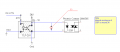
I want to use the TLP-291 optocoupler (OC) as a switch and also isolate the input and output. The output of the OC will activate the Solid state relay (SSR) as shown in the attached circuit.
Problem:
1. If the input of the OC is low i.e 0 V , the collector voltage is 24 V that gets divided through RL and the internal resistance of the SSR. Hence by voltage divider rule, the voltage across the SSR input is around 13.5V.
2. But if the input of the OC is high i.e.5V, the voltage across the input of the SSR should drop down to zero but it is now. When I measure, the voltage is around 4 to 5V.
I don't understand the 2nd point mentioned above. Can any one help me out?
Attachments
-
 17.7 KB Views: 44


