 Facebook
 Google
 GitHub
 Linkedin

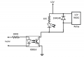
With the circuit shown can someone tell me, and show derivation of, the output current the optocoupler can support?
I am only interested in circuit as shown and do not need variations or suggestions on how to change it.
The KB814 is being driven to saturation and is acting as switch to control the 12V supply to the relay.
Thanks in advance for any help given
Attachments
-
 19.3 KB Views: 23


