Optocoupler As a Switch

Thread Starter

poxusa

Joined Apr 15, 2020
3
Hello Circuits Community.

I am trying to design an AC detection using optocoupler and have been having trouble and thought to reach out for help to the community.

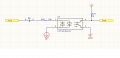
I am inputting 120 VAC via diode (S1M-13-F ) to the optocoupler (LTV-814S-TA1 ) and want the logic on the output to switch between 0V and 3.3V, however, I see output go from 3.3V to 2V when AC is high, so essentially don't pull all the way down.

At 18k @ 120 VAC, should get 6.6mA
At 1k @ 3.3 VDC, should get 3.3mA (which I might be exceeding per datasheet)

Are my resistor values are off and what would values should be?
Also, are my values sufficient for long term operation of 5 years?

Thank you for your suggestions and comments.
 

Attachments

djsfantasi

Joined Apr 11, 2010
9,237
Why do you have a diode in the AC input line? The opto isolator you show is designed for AC operation. The diode effectively blocks half of the signal; one led in the opto never illuminates, effectively only giving a 5o% output cycle.

Secondly, where did you get the 1KΩ value for the pull up resistor? Without more specifics on the output load, my gut says that’s too low a value. Which may prevent the opto from pulling the signal to ground.

With the diode, I’d expect the output to be 1.7V.
 

djsfantasi

Joined Apr 11, 2010
9,237
There are easy ways to calculate the required component values.

R18 = (Vac - 0.7) / If, where If is the LED current from the opto isolator data sheet.

R19 = (3.3 - 0.3) / Ic, where Ic is the current needed by the load. It should be on the datasheet of the load. For a mA load, it calculates out to be 3KΩ.

The diode should be removed.
 

crutschow

Joined Mar 14, 2008
38,505
From the data sheet:
1587003398526.png
As you can see, the minimum Current Transfer Ratio (gain from input to output) is 20%, so for worst-case the output current should never be more that 20% of the input current.

So for 120Vac through 18kΩ, the peak input current is ≈(118*1.4) / 18k = 9.2mA.
For long term operation I would assume the CTR can degrade some, so let's use more than a 10% CTR value.
This means the output current should be no more than 0.92mA or a load resistor of no smaller than 3.6k with a 3.3V suppy.
 

Thread Starter

poxusa

Joined Apr 15, 2020
3
From the data sheet:
View attachment 204512
As you can see, the minimum Current Transfer Ratio (gain from input to output) is 20%, so for worst-case the output current should never be more that 20% of the input current.

So for 120Vac through 18kΩ, the peak input current is ≈(118*1.4) / 18k = 9.2mA.
For long term operation I would assume the CTR can degrade some, so let's use more than a 10% CTR value.
This means the output current should be no more than 0.92mA or a load resistor of no smaller than 3.6k with a 3.3V suppy.
Thank you for your response. Last questions and thank you in advance again.
I have changed input resistance to 81k to reduce power consumption and output to 4.7k. New swing I get when input is high 1.745V and when output is low 3V. The output is connected to the input of the microcontroller that pulls low (per datasheet it’s 40k ohm pull down). I am still not going to logic 0V or at least lower to ensure it’s below logic high detection. Would you please be so kind to point my mistake with new values why my logic does not shift from 3.3V to 0V? Thank you.
 

djsfantasi

Joined Apr 11, 2010
9,237
Thank you for your response. Last questions and thank you in advance again.
I have changed input resistance to 81k to reduce power consumption and output to 4.7k. New swing I get when input is high 1.745V and when output is low 3V. The output is connected to the input of the microcontroller that pulls low (per datasheet it’s 40k ohm pull down). I am still not going to logic 0V or at least lower to ensure it’s below logic high detection. Would you please be so kind to point my mistake with new values why my logic does not shift from 3.3V to 0V? Thank you.
Did you remove the diode? Your results are very close to what I calculated in post #2.
 

Thread Starter

poxusa

Joined Apr 15, 2020
3
Did you remove the diode? Your results are very close to what I calculated in post #2.
Thanks for your response. I did, it did swing closer to zero. After playing around with resistor values I got pretty close to swing from 0.329 to 3.3V. Was hoping to keep diode for surge protection applications. Either way I think I am ok now. Thanks for your replies :)
 
Top