Optimising 433 MHz antenna for RFM69

Thread Starter

has4

Joined Apr 13, 2020
9
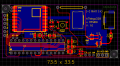
I'm developing an IoT sensor, predominantly for the purpose of door/window sensing. I've developed a custom PCB basesd on an ATMega328 and an RFM69W module.
I'm very impressed with the RFM69 so far, under certain conditions. It can easily go through several brick walls from one end of the house and out the other end. However things change when I'm trying to fit the PCB + antenna into its designated case.
The RSSI drops significantly when I angle the antenna down parallel to the long axis of the case (and parallel to the ground plane of the PCB).
I've optimised these loaded coil antennas but I cannot get the required range when angling the antenna.

Does the RFM69 antenna always have to be perpendicular to its ground plane?
Would I have to change the PCB layout so as to angle the RFM69 at 90 degrees?
Any good ideas for improving this design?
Many thanks
 

Irving

Joined Jan 30, 2016
3,845
Its a while since I did some VHF/UHF stuff but lying that 'loaded whip' down close to its ground plane will seriously impact its performance, as you discovered. In general the antenna should be perpendicular to a ground plane. Three possibilities spring to mind
1. Mount antenna elsewhere in case with small ground plane; e.g. put a right angled bit of ally at one end of PCB and feed through it to antenna - this extends length of case
2. As 1 but mount antenna further away from PCB by at least a couple of coil diameters. This keeps case length the same but increases width or depth
3. Scrap whip and go for pcb printed antenna, possibly on separate parallel PCB. This is the approach taken on my (commercial) wireless door sensors running at 868MHz. Range is across the house, about 12-15m and 3 or 4 walls (running on 2 CR2032 cells).
 

BobTPH

Joined Jun 5, 2013
8,816
How us it oriented with respect to the receiver antenna? Making the parallel definitely improves performance.

Also, I could be wrong about this, but I don’t think a ground plane makes much difference unless it is similar in dimensions to the antenna or larger.

Bob
 

Thread Starter

has4

Joined Apr 13, 2020
9
Thank you both. I think I need to undertake some basic lessons in antenna design and function. I tried some coaxial 433 MHz whip antennas but they were no better than my loaded coil. There are a few designs out there for 2.4GHz PCB trace antennas, haven't yet seen a good one for 433 MHz.
I'm still a little confused where the ground plane comes in when you have a single pole antenna (as opposed to dipole).
If I want to try and connect my antenna further away from the antenna pin of the RFM69, what is the best way of connecting it without messing up impedance matching?
 

Thread Starter

has4

Joined Apr 13, 2020
9
I oriented them both perpendicular to ground, so they were parallel. It does make a big difference.
 

Irving

Joined Jan 30, 2016
3,845
From the HE docs that PeterDeco linked to:

"HE Series antennas are designed for direct PCB mounting. Thanks to the HE’s compact size, they are ideal for internal concealment inside a product’s housing. The HE is also very low in cost, making it well suited to high-volume applications. HE Series antennas have a very narrow bandwidth; thus, care in placement and layout is required. In addition, they are not as efficient as whip-style antennas, so they are generally better suited for use on the transmitter end where attenuation is often required anyway for regulatory compliance. Use on both transmitter and receiver ends is recommended only in instances where a short range (less than 30% of whip style) is acceptable."

The whip antenna is designed to work away from the PCB, not alongside it.

The RF69 output is characterised as +13dBm into 50ohm so any low loss 50ohm mini coax would do.

Have you considered a wire antenna? Interesting video (for 868MHz tho)
 

Thread Starter

has4

Joined Apr 13, 2020
9
Is there any mileage in creating a separate ground plane within the case, with the wire or whip antenna perpendicular to that, and then connecting them via a short coaxial 50Ohm cable?
 

Irving

Joined Jan 30, 2016
3,845
Is there any mileage in creating a separate ground plane within the case, with the wire or whip antenna perpendicular to that, and then connecting them via a short coaxial 50Ohm cable?
That's what I essentially advocated in points 1 & 2 of post #3.

433MHz 1/4 wave is 16.5 - 17cm but thats quite long. Your coiled whip looks like its a 1/4 wave.

On balance I'd try a wire antenna going straight out from PCB for 2 - 3cm before turning at right angles // to PCB. Ideally you'd want a LC matching network for random lengths.

I'm sure you've probably found this, but some useful ideas/discussions here
One that could be interesting is a loop antenna using 10mm wide copper tape . Your box dimensions look like about 5 x 2,5cm so a loop around it would be ~15cm, close to a 1/4 wave...
 

Thread Starter

has4

Joined Apr 13, 2020
9
Thank you! A lot of very helpful discussions on the Lowpowerlab forum.
I've made significant progress with this design:
Salvaged PCB trace antenna (from a GSM module). Connect spiral antenna to this PCB trace (I did not cut the original PCB trace). Connect to RFM69 with proper 50 Ohm cable. I get a huge improvement in RSSIs. I'm thinking of trying to put the antenna inside the case even.
I think all my other attempts failed due to inappropriate bridging connections between the antenna and RFM69 input pad.pcb4.jpgpcb3.jpgIMG_20200613_134101.jpg
 
Top