operational amplifier circuit

RBR1317

Joined Nov 13, 2010
715
Have you ever seen a circuit that works well in theory but not so well in practice? What are the theoretical assumptions regarding the input voltages at the input terminals of an ideal op-amp? Which resistors have current flowing in them? If a resistor has no current flowing through it, can it affect the operation of the circuit?
 

MrAl

Joined Jun 17, 2014
13,704
Hi
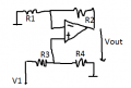
Can someone help why the output voltage Vout /V1=-R2/R1 and dont take the other resistances in consideration
Hello,

In short, all the resistors on the non inverting input go to ground so the voltage on the non inverting input is zero.
Since that voltage is zero, the voltage on the inverting input is also zero. Since that is zero the current through R3 is zero, so the only resistors that determine the gain are R1 and R2 as they are the only ones with any current and voltage drop.
 

Thread Starter

antiantianti

Joined Aug 4, 2016
45
Hello,

In short, all the resistors on the non inverting input go to ground so the voltage on the non inverting input is zero.
Since that voltage is zero, the voltage on the inverting input is also zero. Since that is zero the current through R3 is zero, so the only resistors that determine the gain are R1 and R2 as they are the only ones with any current and voltage drop.
Hi why when the resistors are connected the ground the voltage on the non inverting input is zero ?
thanks
 

RBR1317

Joined Nov 13, 2010
715
...the ground the voltage on the non inverting input is zero ?
Another assumption about an ideal op-amp is infinite open-loop gain, i.e., if there is any voltage difference at all between the input terminals, then the output value would be infinite. So for an inverting op-amp to be working in its linear operating range, the V{+} and V{-} inputs must be at the same voltage. Negative feedback through the circuit forces the V{-} input to be the same voltage as the V{+} input, otherwise the op-amp would just be a comparator with no linear operating range.
 

crutschow

Joined Mar 14, 2008
38,512
The ideal op amp has these basic characteristics:

Both inputs have an infinitely high impedance (no current flows into these terminals with applied voltage).

The open-loop gain is infinitely high, thus there is no voltage difference between the two input terminals when the circuit is stable with negative feedback from the output to the negative terminal.


Using those two characteristics you can answer all your questions using Ohm's law and basic math.
 
Last edited:

MrAl

Joined Jun 17, 2014
13,704
Hi why when the resistors are connected the ground the voltage on the non inverting input is zero ?
thanks
Hi,

As others have pointed out, the op amp is assumed to have zero input current in the non inverting terminal and also the inverting terminal, so that means that no current flows through any of those resistors. If no current flows then there can not be a voltage drop, and since ground is taken to be at zero volts (0v) then the other end of the resistors must be at zero volts too.

That is the theory that pertains to an ideal op amp. In practice we sometimes find a resistor in series with the non inverting input that is there to help counter input current changes with temperature. That's not usually something that is considered in most course work until maybe later in the course. The practical op amp has some input current and it may vary with temperature while the ideal op amp is taken to have exactly zero input current. That allows us to make predictions about the circuit that are usually good enough for many applications without having to do a lot of unnecessary calculations.
 

Thread Starter

antiantianti

Joined Aug 4, 2016
45
Hi this is exactly the point that I dont understand the voltage on the non inverting and the inverting terminal is the same but not necessarily zero only if one of them is connected to the ground ill give an example in the picture if theres are a resistor.the voltage on the inverting terminal is no longer zero I mean there is a resistor between the ground and the inverting terminal so the voltage in no longer zero on the inverting terminal .but still the input voltage is zero because there is no voltage drop .
I mean the virtual ground is only working if one of the terminals is directly connected to the ground ?
 

Attachments

Last edited:

LesJones

Joined Jan 8, 2017
4,511
The Op amp is always attempting to keep the difference in voltage between the + and - inputs at zero by changing the output. In a real op amp there will be a very small voltage between them as the gain is not infinite.

Les.
 

atferrari

Joined Jan 6, 2004
5,012
I dare to suggest the circuit being actually implemented with two or three different sets of Rs. I gained real understanding just by measuring voltages and currents. And I was not even a student trying to solve a problem.

Why are there more than one R going to the non-inverting input? To confuse the issue? Or to make the problem more general?

When I was used to think as below, things became easier for me:

Hello,

In short, all the resistors on the non inverting input go to ground so the voltage on the non inverting input is zero.
Since that voltage is zero, the voltage on the inverting input is also zero. Since that is zero the current through R3 is zero, so the only resistors that determine the gain are R1 and R2 as they are the only ones with any current and voltage drop.
 

dl324

Joined Mar 30, 2015
18,329
the voltage on the inverting terminal is no longer zero I mean there is a resistor between the ground and the inverting terminal so the voltage in no longer zero on the inverting terminal .but still the input voltage is zero because there is no voltage drop .
In an ideal op amp, there is no bias current, so the inverting terminal on both amplifiers is at 0V.
I mean the virtual ground is only working if one of the terminals is directly connected to the ground ?
That's generally how it works... A better way to look at it is to apply the Zero Differential Voltage theorem.
 

Thread Starter

antiantianti

Joined Aug 4, 2016
45
Hi in this problem the out put voltage is Vout =(R4*V1/R4+R3 ) (voltage divider ) did you understand why the output voltage is the same as the voltage though R4?
 

Attachments

MrAl

Joined Jun 17, 2014
13,704
I dare to suggest the circuit being actually implemented with two or three different sets of Rs. I gained real understanding just by measuring voltages and currents. And I was not even a student trying to solve a problem.

Why are there more than one R going to the non-inverting input? To confuse the issue? Or to make the problem more general?

When I was used to think as below, things became easier for me:
Hi there,

There is more than one resistor going to the non inverting terminal because this (from original schematic in post 1) is like a difference amplifier. That means it is supposed to amplify the difference between two inputs where one input goes to R1 (as shown) and the other goes to R5 (shown only as another ground or 0v). So the voltage output is:
Vout=(VinR5-VinR1)*A

where A is the gain set by the resistors.

So you see in his example R5 has 0v input that's all, and if it went to another voltage source which is more typical then we would see the reason for four of the resistors.

There does seem to be one extra resistor on the non inverting terminal however which a true difference amplifier usually doesnt have or need. There's also one extra on the inverting terminal. If either of those goes to a non zero voltage source, they set the output offset voltage, but here they both go to zero so it looks more like just more like a quiz question.
 
Top