opamp driving a mosfet

Thread Starter

doors666

Joined Mar 21, 2014
18
I am using the circuit similar to this page - http://www.daycounter.com/Circuits/Current-Servo/Current-Servo.phtml

I am trying to use IRFZ44, and LMH6657 opamp. The issue I face is that the when the input voltage changes (its like varying dc), the output current is slow to respond due to the gate capacitance of the mosfet. I tried to add a voltage follower buffer after the opamp output (resistor at the emitter, output from emitter). This thing improves the timings, but consumes a lot of power. If the mosfet needs 1A, the voltage follower needs to pass 1A all the time. With 12 v supply, thats 12w of wasted power and excessive heat. I also looked at quite a few mosfet driver chips also, but they all seem to work with digital signal only. Whats my best option here without generating so much heat to add some current capability to the opamp output.
 

ericgibbs

Joined Jan 29, 2010
21,641
hi 666,
When you say the output current is slow to respond, what is the actual delay you measure between say a step input voltage to the OPA and the change in output current.?

What is the 'Current controlled 'device'.? if it inductive that could be a factor in a delayed response.

E
 

DickCappels

Joined Aug 21, 2008
10,661
If you need that much current to drive the MOSFET's gate as fast as you want, and you don't want to use that much current, then you can consider replacing the MOSFET with a MOSFET with lower gate capacitance, a bipolar transistor or Darlington pair, or making a MOSFET/bipolar "Darlington" with the first transistor being a small MOSFET like the 2N7000..
 

Billy4184

Joined Jun 20, 2014
31
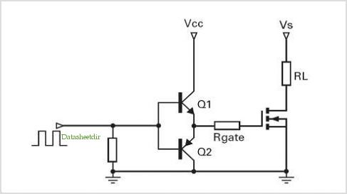
I just had this same problem with a low-side BC337 taking 4us to turn on in a power supply. I believe it is because the collector becomes saturated while it is off and this slows the switching. I solved it by using a totem pole driver behind the MOSFET:


I think this is what DickCappels was suggesting. Instead of the pull-down resistor I have a PWM IC output transistor pulling it down. If you need to invert the above configuration and maintain speed I suggest using a small n-channel MOSFET to pull down the base.

Other than that a schottky diode from base to collector would prevent saturation and switch much faster but will leave ~0.7V on your mosfet gate.
 

crutschow

Joined Mar 14, 2008
38,937
.............................
Other than that a schottky diode from base to collector would prevent saturation and switch much faster but will leave ~0.7V on your mosfet gate.
The circuit you posted can't saturate unless the input goes above Vcc or below ground, so a diode is not needed.
 

Billy4184

Joined Jun 20, 2014
31
@crutschow, I meant it as "other than that", an alternative. I should have been more clear but instead of using the totem pole configuration, a pull-down transistor, prevented from saturating with a schottky diode and driven by the op-amp might also be suitable.
 

Thread Starter

doors666

Joined Mar 21, 2014
18
I dont remember the exact numbers (and it was a different opamp with which i tested), I get about 100-250ns with a voltage follower, and about 1-2us without that. Opamp just doesnt have the juice to charge the gate capacitance fast enough.

The load is purely resistive. Signal will vary from 0-1v approximately. Worst case frequency will be about 500khz. But i still need fast transitioning when ever the voltage level changes.

Isnt totem pole for digital signal. Will it work in this scenario where I am controlling current using a voltage. How much power dissipation I will face with totem pole.
 

Billy4184

Joined Jun 20, 2014
31
My answer was far too general, it was simply about ways to drive MOSFETs faster. I don't think they apply to this kind of circuit since they are digital as you say.

The easiest thing would be to find a mosfet with a very low Qg (yours has 60nC so there is a lot of improvement to be made here). Also find an op-amp with as high an output current as possible.

If you are driving heavy amps and need a big mosfet with a lot of gate charge, I suggest the following (though have never tried it). Set up a constant voltage, high current source at the approximate voltage that your mosfet will need on the gate (you might need to tune it). Then set up a voltage divider on the gate of your big mosfet, using the Rds(on) of a much smaller, faster mosfet as the top resistor. Now control this smaller mosfet with the op amp.

There are mosfets with a Qg of 1nC and an Rds(on) of 100-200mOhms. The bottom half of your divider might be a 1 Ohm, 5W resistor. You might lose around 4W this way.

If you want more control range, reduce the bottom resistor on the divider, but you will waste more energy. At least, this circuit should be very fast! Edit: got a bit mixed up here, control range won't be a problem.

To be clear, this assumes that you are on a very high slope part of the Rds(on) vs. Vgs curve such that a very small change in voltage results in a large change in on-resistance.

Btw, I'm not sure at what point your op amp could become the limiting factor. Someone with more experience with them might be able to help here.
 
Last edited:

crutschow

Joined Mar 14, 2008
38,937
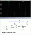
Here's the simulation of a circuit that may work for you. It uses a high speed rail-rail opamp to drive a MOSFET source follower. The delay between input and output is about 30ns.

Buffer.gif
 

Thread Starter

doors666

Joined Mar 21, 2014
18
thanx, I did find some mosfets with much lower input capacitance that fit my needs. I will test it out and see how well it works for me.

Is the mosfet in this circuit operating in the linear mode or saturation mode.
 

RichardO

Joined May 4, 2013
2,270
I dont remember the exact numbers (and it was a different opamp with which i tested),
We need to know what you actually built. Specifically what is the op-amp you used to make the measurements? A quick scan of the LMH6657 datasheet leads me to believe it will work a lot better than what you measured.
 

Thread Starter

doors666

Joined Mar 21, 2014
18
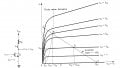
The saturation region (i.e. the region where it acts as a linear amplifier).
Just to make sure, In this image, you mean the region on the right of the dotted dividing line, indicating saturation region.


We need to know what you actually built. Specifically what is the op-amp you used to make the measurements? A quick scan of the LMH6657 datasheet leads me to believe it will work a lot better than what you measured.
I am trying to get rid of the voltage follower. This is the schematic i have at the moment... still trying to fix the wave forms and timings, looks good at higher currents, not so good for low currents.
 

Attachments

bertus

Joined Apr 5, 2008
23,027
Hello,

You need to sign-in on edaboard to see the image under the word this.
Can you copy the image as attachment, so we can see it over here?

Bertus
 
Top