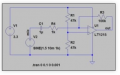
They set the supply bias voltage for the op amp Non-inverting input, as they are both the same value, this will be half of the supply, and so the output will swing around this value.
They set the supply bias voltage for the op amp Non-inverting input, as they are both the same value, this will be half of the supply, and so the output will swing around this value.
About the circuit ...
So if the input is below 1.65 V, and the op amp has a gain of 100 ... if the input is 1.64 V the output of the op amp will be + 1 V? With 3.3 V power rail the circuit won't do much, will it? A few mV to V and the output can't go negative?
Capacitor on the input will block the DC component. All we get is a few mV of signal?
Feedback going to the inverting input, this is suppose to be an amplifier isn't it? Not used as a voltage comparator?
How will the output be "around 1.65 V"?
Thank you so much .!!
Actually i wanted to amplify the microphone signal form input to 3.3V micro-controller compatible . The output of amplifier suppose to go in ADC of micro-controller. This circuit i got on goggle from below link .
Still i do not understand why R1 and R2 is connected in the circuit .
R1 and R2 create an artificial ground at 1/2 of VCC. In an amplifier with +V and -V that pin of the op amp would go to ground. The input signal is centered around ground. In an amp with only a +V you need to set a point at 1/2 VCC to be an artificial ground. The cap on the input blocks any DC component, passing only the AC signal.
To other posters ...
Does he need to reference that signal to 1/2 VCC also?
Is a gain of 100 too much? What does the mike put out in Volts? Just mV then he is okay. 50 mV to 100 mV then he has too much gain doesn't he?
Actually my AIM is to amplify MIC signal which could be (10mV-100mV) to compatible with microcontroller(ADC pin of uC).
Could you modify the schematic for the same.
If 3.3V will be centered around 1.65V so does 1.65V do the job for the same or we need a amplifier without R1 and R2.
Could you guide me a bit more for clarification .
The output of the op amp will be sat at 1.65V DC, with the AC microphone signal superimposed on it, the amplitude of the AC signal is set by the feedback resistors. Without the Half supply offset your output will be at zero dc, it's better to feed the output of the op amp via a capacitor say 10uF to remove the dc offset.
 Facebook
 Google
 GitHub
 Linkedin

 41.6 KB Views: 4


