Facebook
 Google
 GitHub
 Linkedin
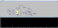
Hello all, i made an op amp to generate a triangular wave, the circuit should integrate the square wave and generate a triangular wave at its ouput, as u can see from the pictures for the part of generating the square wave i could do that, but for the part of triangular wave i think i made a mistake or so.
First of all i chose a common value of R9, which is 10k then i calculated the capitance for having an integration at 10khz, i found out C=1/2 πR*F what i obtained is a capacitance of C= 1,6nF at this point i calculated R4 in order to have fc=fmin/10 and i obtained that R2>10/2 π C1*fmin where fmin is 1KHz
What i obtained is R2 needs to be atleast 1MegaOhm, which is the value i chose. Now as last i chose the gainbandwidth to be atleast 10 times the fmaxso its 100KHz (the op amp i chose has 550 kHz to 650 kHz.
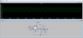
I cant understand the mistake i made, calculations side seem to be right, then why i get that wave from in output?
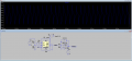
First of all i chose a common value of R9, which is 10k then i calculated the capitance for having an integration at 10khz, i found out C=1/2 πR*F what i obtained is a capacitance of C= 1,6nF at this point i calculated R4 in order to have fc=fmin/10 and i obtained that R2>10/2 π C1*fmin where fmin is 1KHz
What i obtained is R2 needs to be atleast 1MegaOhm, which is the value i chose. Now as last i chose the gainbandwidth to be atleast 10 times the fmaxso its 100KHz (the op amp i chose has 550 kHz to 650 kHz.
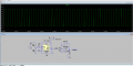
I cant understand the mistake i made, calculations side seem to be right, then why i get that wave from in output?
Attachments
-
 52.8 KB Views: 27
 -
 53.3 KB Views: 26
 -
2.4 KB Views: 2