Facebook
 Google
 GitHub
 Linkedin
Hey Guys, I'm new to the forum, I have recently joined but I have always had a browse through the forum when ever I needed help with a circuit or when I was curious about a circuit.
I have come across this type of OP-AMP circuit and I'm having problems trying to figure out how it works... I have tried books, simulation programs and deriving it, but I can't figure it out. Is this a voltage comparator? Open Loop configuration?
Circuit 1) First I will show you how I believe it should work.
Circuit 2) I'll show you the actual circuit.
Circuit 1) How I think circuit (2) should work...
Circuit 1 with Vs = 0V LED = ON

I have taken out the resistors from circuit 2 as all they do is:
-Rth - Limits the current to the LED (In Circuit 1 the current is about 435A, needs to be limited by Rth)
-R1 and R2 in Circuit 2 create a voltage divider from 15V to get 1.05995V (Vth: Thevenin's equivalent voltage) as I have in Circuit 1.
Circuit 1 with Vs = 1V LED = OFF

From this I figured that when Vs = 0V, Vout will be -15V, providing -15V for the LED that is revered biased for it to turn on... of course I need a resistor in series because -15V is too much voltage for the LED... In circuit two I did some calculations and managed to get the current to be about 4mA across the LED, which is what I need as well as a 13.8V drop across the resistor (Rth) so that 1.2V is left to turn on the LED. (1.2V is the typical voltage drop across this type of LED Im using).
Where Rth is the Thevenin's equivalent of R1 and R2.
and Vcancelouterror in Circuit 1 is Vth, the Thevenin's equivalent voltage.
where Rth = (R1*R2)/(R1+R2) and Vth = 15V*(R2/R1+R2)
Vth is the voltage divider rule, and the 15V comes from circuit 2 if you have a look.
-----------------------------------------------------------------------
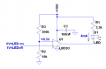
2) What the circuit actually looks like...

One thing I noticed is that I think the voltage drop across this diode is actually about 0.7-0.9V? Where my LED needs about 1.2V... I don't think this matters, what I don't understand is why I'm not getting -15V and 0V at the output any more?
And back to my main question:
Why doesn't Circuit 1 behave like Circuit 2?
-----------------------------------------------------------------------
How I found my R1 and R2 values where using Excel and the above formulas for the Rth and Vth I required which are 3450 Ohms and 1.05995V respectively. Vs is 1.05995 instead of 1V because the 59.95mV comes from the errors of the op-amp (Offset Voltage, I know this offset value seems massive, this is because I am using a special opamp designed for students)
Vth of 1.05995V I need so that I can cancel the Vs signal of 1.05995V, so that my Vout is 0V.
I need Rth to be 3450 Ohms because if I have 15V going through the diode then 1.2 will drop across the diode so then I'm left with 13.8V which needs to be dropped across resistor Rth... 13.8V/4mA = 3450 Ohms
Excel Calculations:

-----------------------------------------------------------------------
If anything seems unclear please tell me and I will reply and clear up anything I haven't clearly stated... I know sometimes I have trouble explaining things properly. Any positive criticism I am open to
I thank you guys in advanced and appreciate your time
-Kamil
I have come across this type of OP-AMP circuit and I'm having problems trying to figure out how it works... I have tried books, simulation programs and deriving it, but I can't figure it out. Is this a voltage comparator? Open Loop configuration?
Circuit 1) First I will show you how I believe it should work.
Circuit 2) I'll show you the actual circuit.
Circuit 1) How I think circuit (2) should work...
Circuit 1 with Vs = 0V LED = ON

I have taken out the resistors from circuit 2 as all they do is:
-Rth - Limits the current to the LED (In Circuit 1 the current is about 435A, needs to be limited by Rth)
-R1 and R2 in Circuit 2 create a voltage divider from 15V to get 1.05995V (Vth: Thevenin's equivalent voltage) as I have in Circuit 1.
Circuit 1 with Vs = 1V LED = OFF

From this I figured that when Vs = 0V, Vout will be -15V, providing -15V for the LED that is revered biased for it to turn on... of course I need a resistor in series because -15V is too much voltage for the LED... In circuit two I did some calculations and managed to get the current to be about 4mA across the LED, which is what I need as well as a 13.8V drop across the resistor (Rth) so that 1.2V is left to turn on the LED. (1.2V is the typical voltage drop across this type of LED Im using).
Where Rth is the Thevenin's equivalent of R1 and R2.
and Vcancelouterror in Circuit 1 is Vth, the Thevenin's equivalent voltage.
where Rth = (R1*R2)/(R1+R2) and Vth = 15V*(R2/R1+R2)
Vth is the voltage divider rule, and the 15V comes from circuit 2 if you have a look.
-----------------------------------------------------------------------
2) What the circuit actually looks like...

One thing I noticed is that I think the voltage drop across this diode is actually about 0.7-0.9V? Where my LED needs about 1.2V... I don't think this matters, what I don't understand is why I'm not getting -15V and 0V at the output any more?
And back to my main question:
Why doesn't Circuit 1 behave like Circuit 2?
-----------------------------------------------------------------------
How I found my R1 and R2 values where using Excel and the above formulas for the Rth and Vth I required which are 3450 Ohms and 1.05995V respectively. Vs is 1.05995 instead of 1V because the 59.95mV comes from the errors of the op-amp (Offset Voltage, I know this offset value seems massive, this is because I am using a special opamp designed for students)
Vth of 1.05995V I need so that I can cancel the Vs signal of 1.05995V, so that my Vout is 0V.
I need Rth to be 3450 Ohms because if I have 15V going through the diode then 1.2 will drop across the diode so then I'm left with 13.8V which needs to be dropped across resistor Rth... 13.8V/4mA = 3450 Ohms
Excel Calculations:

-----------------------------------------------------------------------
If anything seems unclear please tell me and I will reply and clear up anything I haven't clearly stated... I know sometimes I have trouble explaining things properly. Any positive criticism I am open to
I thank you guys in advanced and appreciate your time
-Kamil