Op Amp Integrator Simulation problem

Thread Starter

Sebas123

Joined Jun 12, 2015
4
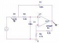
I have an assignment that consist in making a integrator circuit. I was simulating it in OrCAD and the output doesnt match what i expected. It is supposed to invert and integrate the inputt signal but none of that happens. I attached the schematic with the output. The input is a square waveform from -1 to 1 with 6.66mHz
 

Attachments

MikeML

Joined Oct 2, 2009
5,444
You input shows a square wave with a period of 6.66ms, which is ~150Hz. Is that what you intended?

Your circuit is a Sallen-Key low-pass filter with a lot of peaking near its corner frequency of 273Hz. Since you are exciting it with 150Hz, it will pass it, but the peaking will greatly distort the wave.

Since the input goes to the non-inverting input of the opamp, how can it invert the signal? Note that for frequencies below the cut-off, the phase shift is 0 deg.

275.gif
 

Thread Starter

Sebas123

Joined Jun 12, 2015
4
I am sorry, yes its a 150Hz frecuency signal, the 6.66ms is the period. You are right, it doesnt invert the signal. Just one more thing. How come the peaking distort the wave? I just dont get it. If the frecuency was lower, lets say 50Hz, the output should be more similar to the expected triangle form? Thanks a lot.
 

MikeML

Joined Oct 2, 2009
5,444
What is the goal? Is it to take a 150Hs square wave, low-pass filter it to make it look like a 150Hz sine wave (get rid of the harmonics)?
 

Thread Starter

Sebas123

Joined Jun 12, 2015
4
Well, its the first part of a proyect our signals and system teacher gave us. For now im just trying to understand every single aspect of it. We have to make the discrete convolution of the system ( The low pass filter ) and get in the lab the responses to different signals. The thing is that i was expecting an ideal integrator and not taking into account the frecuency stuff. My bad i think... i just wanted to know what should i expect in the lab when i put together the circuit and test it.
 

MikeML

Joined Oct 2, 2009
5,444
Here I show you the response to two different frequencies of a square wave, namely 150Hz and 273Hz. Note what happens if the frequency of the square wave matches the resonant frequency of the filter. I had previously learned that the resonant point of your circuit is 273 Hz by sweeping it with a sinosoid.

If you feed in a squarewave, the "filter" passes only the square wave's fundamental, suppressing its harmonics.

Note the amplification that takes place because of the filter Q. Also notice that due to the Q of the filter, it takes several cycles of the input waveform for the filter output to achieve its steady-state amplitude.

I will let you do the mathematical analysis to support what the simulation has already showed...

275a.gif
 

Thread Starter

Sebas123

Joined Jun 12, 2015
4
Thanks a lot! Yes, i did some research about Sallen key config and found what you are talking about. Also i asked my teacher and gave me the same info you had already posted. Thanks a lot again, you have helped me a lot.
 
Top