Op-amp feedback

LvW

Joined Jun 13, 2013
2,037
What I meant is: if the feedback makes the output drop, then it's negative; and if it makes it raise, then it's positive.
Just to complete the sentence:

..if the feedback makes the output drop - and when this action was caused by an unwanted output increase - then it's negative.

Thus, negative feedback counteracts (reduces) output changes.
That is the reason for the observed gain reduction caused by negative feedback. But this is a desired effect.
 

Jony130

Joined Feb 17, 2009
5,600
What I meant is: if the feedback makes the output drop, then it's negative; and if it makes it raise, then it's positive.
As you can read in post 2, Negative feedback tends to equilibrium (balance).
Negative feedback wants to "restore" the previous state of the circuit.
 

MikeML

Joined Oct 2, 2009
5,444
MikeML - ...
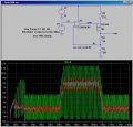
Therefore, back to your example circuit: I think, it is no surprise that it oscillates.
There are two reasons:
1.) As can be seen by comparing (in your simulation results) the gate ac voltage with the ac voltage at the opamp input, the overall feedback factor is larger than unity (that means: The gain of the FET amplifier is larger than the max. allowed value of 5, given a 4:1 resistor ratio in the drain path).
2.) You have selected a POWER MOSFET (by accident or intentionally?) with very bad high-frequency characteristics. For example, the input capacitance is in the order of 0.5nF. As a consequence, the gain drops already in the lower kHz range.
________
Thus, it is really no surprise that the circuit oscillates because the FET circuit acts as a lowpass with corresponding additional phase shift.
I think, the situation will be different if a small-signal MOSFET with the correct gain value is used.

Therefore, I think my general comments as given in former posts still hold:

The circuit under discussion may oscillate or not - depending on the frequency response of both active elements (opamp and FET) as well as on the overall feedback factor which is set by the two drain resistors.

Final comment: Anybody who is not familiar with the concept of stability and oscillations could use this feedback example to see and understand why oscillations might occur (or not).

EDIT:
I have replaced the Power mosfet by a small-signal P-Jfet (2N2608) - and did some simulations (TRAN). As a result, the circuit was absolutely stable for a varity of opamp models (741, LM328, AD712, LT1007,...).
In the original conception, I needed a power FET, because I was driving a large current into the load. For the lightly loaded example I posted, I replaced the PFET with a half dozen small-signal PFET, including BSS84, TP2640, VP2106, etc and the they all still oscillate, so choosing a different PFET doesn't stabilize the circuit...

As to your point about the loop gain, I introduced an un-bypassed resistor into the PFET's source, and the circuit does become stable, albeit with overshoot and ringing, at values of that resistor greater than 400Ω. That reduces the loop gain to approaching one....
 

Attachments

LvW

Joined Jun 13, 2013
2,037
In the original conception, I needed a power FET, because I was driving a large current into the load. For the lightly loaded example I posted, I replaced the PFET with a half dozen small-signal PFET, including BSS84, TP2640, VP2106, etc and the they all still oscillate, so choosing a different PFET doesn't stabilize the circuit...

As to your point about the loop gain, I introduced an un-bypassed resistor into the PFET's source, and the circuit does become stable, albeit with overshoot and ringing, at values of that resistor greater than 400Ω. That reduces the loop gain to approaching one....
I think, your results suport my claim that the stability of the circuit configuration under discussion depends on the particular properties of the active devices.
I only can repeat that with P-Jfet (2N2608) and "your" drain resistors (2k, 0.470k) the circuit was stable. Some comments/explanations follow:

1.) DC concept: Because the P-Jfet needs a positive Vgs the source voltage was reduced to 8 volts. More than that, in my circuit the inverting opamp terminal was connected not to ground but to a dc voltage of +1V. This has the advantage that the voltage across the 470 ohm resistor was forced by feedback to be also app. 1V - and the current through the resistor chain has a value that allows good control.
Note that for a grounded inv. terminal (as in your circuit) this current must produce a tiny voltage in the micro-volts range.
EDIT: I just have discovered that also in your simulation the inv. terminal never reaches ground potential. Thus, the sentence with the "tiny" voltage does not apply anymore.
2.) Stabilization: Yes - it is to be expected that a source resistor (negative feedback) reduces the gain and can stabilize the circuit. I have applied another method. After increasing the FET gain (larger resistor values without changing the ratio) also my circuit became unstable.
However, it was possible to stabilize it by placing a capacitor with a small series resistor across both drain resistors (between drain and ground).
The time constant was chosen with respect to that frequency at which the loop gain (without stabilization) is unity.
The stabilization effect was justified with a TRAN analysis as well as loop gain analyses (phase margin determination).
3.) Evaluation: This stabilization method is known from the principle of linear voltage regulation - and this is no surprise: The circuit under discussion resembles the well-known working principle of a linear voltage regulator with a FET as path element. And from these circuits we know that they tend to instability, but can be stabilized with such a "lossy" capacitor across the output.
 
Last edited:
Top