op-amp comparator question

Thread Starter

Raziel_LOK

Joined May 22, 2012
6
Hello everyone, I'm new here and I was searching about op-amps and comparators.

As far as I found, I know how to use a op-amp as comparator, the problem now is that I want a exact comparator, for example:

I need a input of 2V to pass 5V, but any other value in a decimal precision of 0,1V up or down should pass 0V. Is that possible with op-amps? any easy way to do that? There are cheap IC (or a simple circuit) to this especific function?

Thank you.
 

MrChips

Joined Oct 2, 2009
35,117
Use a voltage divider or similar circuit to provide a reference voltage of 2V (or 1.5V). Apply this to the inverting input.
 

Thread Starter

Raziel_LOK

Joined May 22, 2012
6
I googled it, but on the simulator the op-amp has only 3 pins (falstad) so I think that's why this window comparator didn't worked. I will get a new circuit simulator and test it.

basically I want to create a kind of circuit to control 4 switches (or more) with only two wires. One wire to ground and other for voltage, and on the other side each switch is triggered depending on the voltage.

If there is any other solution cheaper than op-amps. Please let me know.

Thank you all for the replies.
 

Ron H

Joined Apr 14, 2005
7,063
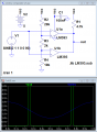
Do it as in the attached schematic.

You can simulate it with LTspice, but you will have to import the LM393 model first.

Rich (BB code):
* LM393 VOLTAGE COMPARATOR "MACROMODEL" SUBCIRCUIT
* CREATED USING PARTS VERSION 4.03 ON 03/07/90 AT 14:17
* REV (N/A)
* CONNECTIONS:   NON-INVERTING INPUT
*                | INVERTING INPUT
*                | | POSITIVE POWER SUPPLY
*                | | | NEGATIVE POWER SUPPLY
*                | | | | OPEN COLLECTOR OUTPUT
*                | | | | |
.SUBCKT LM393    1 2 3 4 5
*
  F1    9  3 V1 1
  IEE   3  7 DC 100.0E-6
  VI1  21  1 DC .75
  VI2  22  2 DC .75
  Q1    9 21  7 QIN
  Q2    8 22  7 QIN
  Q3    9  8  4 QMO
  Q4    8  8  4 QMI
.MODEL QIN PNP(IS=800.0E-18 BF=2.000E3)
.MODEL QMI NPN(IS=800.0E-18 BF=1002)
.MODEL QMO NPN(IS=800.0E-18 BF=1000 CJC=1E-15 TR=807.4E-9)
  E1   10  4  9  4  1
  V1   10 11 DC 0
  Q5    5 11  4 QOC
.MODEL QOC NPN(IS=800.0E-18 BF=20.29E3 CJC=1E-15 TF=942.6E-12 TR=543.8E-9)
  DP    4  3 DX
  RP 3  4 46.3E3
.MODEL DX  D(IS=800.0E-18)
*
.ENDS
 

Attachments

crutschow

Joined Mar 14, 2008
38,763
..............................
basically I want to create a kind of circuit to control 4 switches (or more) with only two wires. One wire to ground and other for voltage, and on the other side each switch is triggered depending on the voltage.

If there is any other solution cheaper than op-amps. Please let me know.
If you want to control 4 or more switches from one line then it may be simpler to use an A/D converter such as this and a decoder. If you connect a 4-bit decoder such as the CD4514 or CD4515 to the four most significant-bit outputs of the A/D You will have 16 equal spaced selection voltages over the full scale input range of the A/D to select one of the 16 outputs of the decoder.
 

Ron H

Joined Apr 14, 2005
7,063
If you want to control 4 or more switches from one line then it may be simpler to use an A/D converter such as this and a decoder. If you connect a 4-bit decoder such as the CD4514 or CD4515 to the four most significant-bit outputs of the A/D You will have 16 equal spaced selection voltages over the full scale input range of the A/D to select one of the 16 outputs of the decoder.
If the switches are widely spaced, this is going to require an A/D and decoder at each switch location. A microcontroller at each location might be the cheapest solution, but it requires programming.
Without programming, I would use a window comparator, like the one I posted, at each location, but with the thresholds set at 10%, 30%, 50%, and 70% of Vcc. The control steps would be 20%, 40%, 60%, and 80% of Vcc. For example, if Vcc=5V, then the thresholds would be 0.5V, 1.5V, 2.5V, and 3.5V. The control levels would be 1V, 2V, 3V, and 4V. This would give good noise immunity, and would fit into the common mode range of LM393.
 

crutschow

Joined Mar 14, 2008
38,763
Any suggestion of a beginners tutorials about AD converters? :D
Here's a simple starter on ADCs.

Unfortunately there's likely a significant learning curve if you are not familiar with ADCs and digital circuits so it will take a fair amount of study on your part to become familiar with those devices.

Conceptually you would use a simple clock (such as a 555 connected as an astable multivibrator) to provide a trigger to the A/D /CONVST input to periodically trigger the ADC to do a conversion. The converted value 4 MSBs (most significant bits) of the ADC then go to the decoder (CD4028 for 10 outputs, CD4514/CD4515 for 16 outputs). The decoder outputs then drive relays to do the switching.

If you use the 4 MSBs to the decoder with a 5V input full-scale for the A/D, then the break voltages for each switch voltage will be at 5V/16 or 0.312V. Thus 0-.312V enables the first output, .312V-.624V enables the second output, etc. You would set the switch input levels to the A/D to be at the middle of each interval step.
 

WBahn

Joined Mar 31, 2012
33,130
I want a exact comparator
You want to be careful about using "exact" when it comes to any kind of engineering. With few exceptions, engineering is about specifications that dictate what approximations are good enough.

I need a input of 2V to pass 5V, but any other value in a decimal precision of 0,1V up or down should pass 0V. Is that possible with op-amps? any easy way to do that?
I'm not sure I've extracted the right meaning from this. I'm assuming that you are from a place where the comma is used as the radix point (to separate the whole portion of a number from the fractional part)? I'm used to using the period for this purpose, so keep that in mind below.

If I understand you correctly, you want the circuit to output 5V when the input is between 1.9V and 2.1V and to output 0V otherwise. Correct?

There are a number of ways of doing this. You talk about four switches. If you are trying to detect which of several ranges the input voltage lies within, you might look at using a quad comparator IC and then some very simple digital logic (think XOR gate) to process the outputs.
 

Thread Starter

Raziel_LOK

Joined May 22, 2012
6
I think I will test it with the window comparator, I'm not familiar with digital circuits or decoders. So as someone said above, it may take a lot of time until I can work well with these devices.

Actually what I want is to control the buttons of a generic xbox pad with just one wire. This is for testing a circuit by sending commands to the pad by the computer or by a series of buttons without needing a wire for each button.
 

Thread Starter

Raziel_LOK

Joined May 22, 2012
6
You want to be careful about using "exact" when it comes to any kind of engineering. With few exceptions, engineering is about specifications that dictate what approximations are good enough.


I'm not sure I've extracted the right meaning from this. I'm assuming that you are from a place where the comma is used as the radix point (to separate the whole portion of a number from the fractional part)? I'm used to using the period for this purpose, so keep that in mind below.

If I understand you correctly, you want the circuit to output 5V when the input is between 1.9V and 2.1V and to output 0V otherwise. Correct?

There are a number of ways of doing this. You talk about four switches. If you are trying to detect which of several ranges the input voltage lies within, you might look at using a quad comparator IC and then some very simple digital logic (think XOR gate) to process the outputs.
Basically is it, each button on the pad is common ground and the signal part send a specific voltage when measured, so I want to output this voltage (in truth I need just to wire it to ground to activate the button) to activate the respective button. As I said above, I just need to use less wires to control each button.

Thanks
 

Wendy

Joined Mar 24, 2008
23,811
Just curious, while op amps can be used as comparators, they really aren't the same thing. Are you aware of the distinction?
 

Thread Starter

Raziel_LOK

Joined May 22, 2012
6
Just curious, while op amps can be used as comparators, they really aren't the same thing. Are you aware of the distinction?
I really don't know what these differences exact means, but for me it looks that a comparator fits better for what I'm trying to accomplish, I have some notions about electronics but I'm not a kind of expert, I just do what works for me and I try to learn something better after. If the simulation that Ron H posted using LM393 do a good job for me, I will use it and then get into AD converters and decoders, if that works better for this purpose.
 

Wendy

Joined Mar 24, 2008
23,811
A comparator is a true digital gate, a op amp is a linear component. The first thing that jumps out from this distinction is speed. A comparator switches much, much faster (think nanoseconds), while an op amp has a spec referred to as slew rate, which is measured in V/s (or V/µs more typically).

A lot of comparators use a digital technique called open collector, which is exactly what it sounds like. A pull up resistor, typically 10KΩ, is required.

Op amps do not handle input voltages that are close to the power supply rails well, if you get within 0.5V of ground or Vcc they stop working (there are specific op amps this is not true, and some op amps stop working within 2V). Comparators do not typically have this design limitation.

For the stuff I like to to I use a LM393 (a dual comparator) or a LM339 (a quad), both are open collector, both are very inexpensive.

Hope this helped.
 
Top