The gain of an amplifier built using an opamp are largely determined by the values of the component connected around the opamp, not the intrinsic gain of the opamp IC itself, as the gain of an opamp IC can run into millions.
You will need to make sure you fully understand why this is so and how the gain of the circuit is calculated.
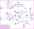
when you connect the output of the op amp to the negative input terminal you create a voltage follower(the two on the left side of the circuit). By going through a resistor back to the negative terminal the output voltage becomes a multiple of the input voltage.
Av=(R2/R1)+1=1.33
so if Av=1.33 and the voltage at point #8 is 4V, then the input voltage is 4/1.33=3V(point 9)
calculating for the voltage drop across the 30k i would get 12V at point #11. is that correct?
when you connect the output of the op amp to the negative input terminal you create a voltage follower(the two on the left side of the circuit). By going through a resistor back to the negative terminal the output voltage becomes a multiple of the input voltage.
Av=(R2/R1)+1=1.33
so if Av=1.33 and the voltage at point #8 is 4V, then the input voltage is 4/1.33=3V(point 9)
calculating for the voltage drop across the 30k i would get 12V at point #11. is that correct?
You're getting closer. Your equation is for a noninverting feedback amplifier. A4 is in an inverting configuration. What is the equation for an inverting amp?
Also - point 9 is at virtual ground (0V).
That's correct. Another way of looking at it is to realize that:
1. The inverting input of V4=0V, due to the negative feedback (both inputs will be at the same voltage).
2. Op amp input currents are zero. Therefore, the current through the 30k source resistor will be equal to the current through the 10k feedback resistor.
3. Since you know that V4=+4V, then V3=-12V.
I repeat: You really need to read and understandthis section of the forum's tutorials, not just the equation for the gain of an inverting amplifier.
I dont understand how 6 is 4.5V ..... i know i/p currents to opamps are 0 .... on what basis do you say that 0.5V will drop over the 10k connected to V2?
If you say that op-amp's i/p are at same potential due to fb .... that is true only for -ve feedback ..... A3 has positive FB ...
I dont understand how 6 is 4.5V ..... i know i/p currents to opamps are 0 .... on what basis do you say that 0.5V will drop over the 10k connected to V2?
If you say that op-amp's i/p are at same potential due to fb .... that is true only for -ve feedback ..... A3 has positive FB ...
I know it's confusing, because the feedback is to the +pin on A3, but A3 has negative feedback, because A4 is an inverting amplifier. The signal fed back to 6 has the opposite sense of 3, i.e., if 3 goes up, 6 goes down. That's negative feedback.
I know it's confusing, because the feedback is to the +pin on A3, but A3 has negative feedback, because A4 is an inverting amplifier. The signal fed back to 6 has the opposite sense of 3, i.e., if 3 goes up, 6 goes down. That's negative feedback.
do you mean to say since the POSITIVE feedback to A3 is via an inverting opamp (A4) it actually becomes NEGATIVE feedback?
it is logical and makes a lot of sense .... so when analyzing i consider A3 to be -ve FB ... then it is easy 6 = 4.5V .... 0.5V across 10K and no current in i/p of A3 makes same current through the other 10k making 0.5V across it ..... making o/p of A4 = 4V, no current in i/p of A4 makes current through same making V = 12V, considering A4 is in inv mode and the o/p is +ve the V i/p must be -ve hence V3 = -12 ....
what of the currents ..... we have 0.5/10K flowing out of A2 and through the other 10K where does it disappear???
do you mean to say since the POSITIVE feedback to A3 is via an inverting opamp (A4) it actually becomes NEGATIVE feedback?
it is logical and makes a lot of sense .... so when analyzing i consider A3 to be -ve FB ... then it is easy 6 = 4.5V .... 0.5V across 10K and no current in i/p of A3 makes same current through the other 10k making 0.5V across it ..... making o/p of A4 = 4V, no current in i/p of A4 makes current through same making V = 12V, considering A4 is in inv mode and the o/p is +ve the V i/p must be -ve hence V3 = -12 ....
what of the currents ..... we have 0.5/10K flowing out of A2 and through the other 10K where does it disappear???
thanks ... i was wondering that can this be mathematically solved/proved WITHOUT assuming A3 has -ve fb ... I tried but w/o V4 and/or V3 ....we just end up with 1 eq having 2 variables (V4= -V3/3) ....

 Facebook
 Google
 GitHub
 Linkedin




 do you mean to say since the POSITIVE feedback to A3 is via an inverting opamp (A4) it actually becomes NEGATIVE feedback?




