One shot oscillation when hot

Thread Starter

graybeard

Joined Apr 10, 2012
99
I have a Smiths tachometer out of a vintage Volvo P1800 that is reading very high at hot temperatures.

The tachometer is implemented using a blocking oscillator as a one-shot that is triggered with each ignition pulse. It is triggered by the car's coil current via the transformer used for the blocking oscillator. Normally, an ignition current pulse generates a nice, wide one-shot current pulse through the tachometer's ammeter to indicate the engine RPMs.

Here are the schematics for the tachometer:

1661549983801.png

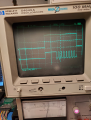
The transistor and the cap have been replaced with new units and the tachometer functions well under about 124 degrees F. But at and above 124 degrees F, the one-shot appears to oscillate after the one-shot pulse is done and before the end of the calibration pulse. Here is a scope photo with the calibration signal on top and the one-shot signal on the bottom. Below about 124 degrees F, there is simply a one shot pulse on the bottom trace, but above about 124 degrees F, the signal seems to oscillate after the one-shot pulse ends:

1661550327339.png

I do not have an intuitive understanding of how blocking oscillators work and I have no clue as to what might happen to an old tachometer that could cause the signal to oscillate like this.

I would appreciate any help you all might have in helping me to intuitively understand the operation of this one-shot circuit and to try to diagnose what might be causing this oscillation at higher temperatures.

Thanks in advance.
 

Attachments

MisterBill2

Joined Jan 23, 2018
18,176
The most suspect part nowis that thermistor, or possibly the resistor it is shunting. If you have any data on the thermistor you could check to see if it is within tolerance.
 

Alec_t

Joined Sep 17, 2013
14,280
I agree with MisterBill2.
A 10°C shift in temperature changes the transistor Vbe by about 20mV. Considering that a germanium transistor has a turn-on threshold of only about 200mV that shift is very significant and can easily make the difference between the transistor conducting or not. Hence the need for the thermistor (presumably a PTC one) for temperature compensation.
 

MisterBill2

Joined Jan 23, 2018
18,176
Perhaps the capacitor and transistor were OK, if it worked as intended at lower temperatures. That would tend to at least merit additional checks prior to replacing parts. How close a substitute IS that replacement transistor? That could also be an issue.
So now the question of is this during the malfunction time period or not,
Usually a blocking oscillator is on the verge of oscillation, and some external trigger pushes it into oscillation for either a cycle or several cycles. Usually some RC time constant halts the oscillation, either after one cycle or a few cycles.
 

Thread Starter

graybeard

Joined Apr 10, 2012
99
Guys, thanks so much for the inputs. They are very helpful.

Smiths used a germanium transistor marked "MT59/A" in their second generation electronic tachometers. I haven't been able to find any information about these transistors. I have successfully repaired a lot of these tachometers using an NTE 176 germanium transistor, so I THINK it is close enough.

I can force the one-shot to oscillate by heating up the circuit using a hair dryer. This morning, I did that and then hit the thermistor only with freeze spray. That stopped the oscillation. So I think we are closing in on the problem.

It is not clear to me why an out-of-spec thermistor would cause this oscillation. I assume the feedback needed for the one-shot is coming from the 30 turn to 90 turn windings of the transformer. I am guessing that too much current through the transistor is triggering the oscillation, but I am really weak with analog circuits like this.

I have no clue as to what value of thermistor I should use to replace this one. I know that the thermistor compensates for temperature variations in the copper in the tachometer's windings, but I am not sure if it is compensating for the winding in the ammeter and/or one or all of the transformer windings. Do any of you have any idea as to how to calculate the value needed for that circuit?

Again, I really appreciate all of your help on all of this.

FYI, I am recovering from a knee replacement, so I have limited times I am feeling well enough to get back into the lab to work on this...
 

boostbuck

Joined Oct 5, 2017
501
Are there any markings on the thermistor to help define it?

Since the circuit works when cold, pulling the thermistor out of circuit and measuring it's resistance at 25C will help specify a replacement.
 

MisterBill2

Joined Jan 23, 2018
18,176
The way the tach is supposed to work is that the oscillator delivers a constant width pulse every time the ignition fires, and the inertia of the tachometer meter averages those pulses against the spring to provide a reading. Ay least one version of the SUN tach used a mechanical relay for the same function. If it could be made to deliver constant width pulses over the temperature range, a 555 timer IC might work well, unless there are multiple non-linear responses cancelling each other out. My efforts at tachometers involved the LM2917, which was as close to perfectly linear as I could read on the RPM meter. Only the digital counter tach circuits were better, but with a one second count time they were always behind. (I did have to use a digital frequency multiplier to get correct readings for RPM on a V8 engine with the one second timebase.)
And I am really wondering about the 2r2 ohm resistor. What value does it read with the thermistor in parallel?

AND, how close to correct are the RPM readings when the temperature is not hot??
 

Thread Starter

graybeard

Joined Apr 10, 2012
99
I will have to pull the thermistor and resistor off of the PCB to measure them, which I will do when my knee is next ready for a few minutes in the lab.

I do know that a resistor in parallel with a thermistor linearizes the thermistor's curve.

I am a little surprised that the thermistor could cause the oscillation because the resistance of the thermistor/resistor should be swamped by the resistance of the 50 ohm pot, which is always set somewhere in the middle.

When the tachometer circuit is cold and functioning properly, the readings are within +- 100 RPMs compared to the calibration signal, so these tachometers are surprisingly accurate when they are working properly.
 

MisterBill2

Joined Jan 23, 2018
18,176
It looks like you can probe them from the top, no need to remove them and risk doing damage. And at the same time you can measure that calibration pot and see what value it is set at.
And again, is the RPM indication correct when the tach is not hot? Also, has anything in the ignition circuit been added or changes, that might affect the current through the tach??? The cause might possibly be external.
 

Thread Starter

graybeard

Joined Apr 10, 2012
99
The car is a 73 Volvo P1800 with a stock set of points and coil. The tachometer had failed completely a few years ago. Replacing the transistor with the NTE transistor repaired the tachometer which has worked well for a few years until this year. It started reading a bit high when hot and eventually started reading very high when hot. That was when the tachometer was sent back to me again.

The tachometer fails the same way in the car and on the bench. I am using a Digilent Analog Discovery 2 as a square wave function generator connected to a custom high current amplifier I use to simulate a coil current waveform. I am generating a very clean calibration signal. I don't think anything with the triggering signal is causing this either in the car or on the bench. I can see the oscillation suddenly start on the scop as the temp threshold is exceeded and the needle jumps way up at that time.

As I said in the post above, when the one-shot is not oscillating at high temps, the tachometer calibration is pretty accurate, within +-100 RPM at every point on the scale. It reads dead on for most of the points on the scale.

In-circuit, the thermistor/resistor in parallel reads 1.9 Ohms at 74 degrees F. The pot is set to 16.8 Ohms when the tachometer is calibrated and working well at colder temps. The resistances were taken with my Agilent 34401A DMM. The temperature was taken with a generic IR laser spot thermometer.
 

MisterBill2

Joined Jan 23, 2018
18,176
The car is a 73 Volvo P1800 with a stock set of points and coil. The tachometer had failed completely a few years ago. Replacing the transistor with the NTE transistor repaired the tachometer which has worked well for a few years until this year. It started reading a bit high when hot and eventually started reading very high when hot. That was when the tachometer was sent back to me again.

The tachometer fails the same way in the car and on the bench. I am using a Digilent Analog Discovery 2 as a square wave function generator connected to a custom high current amplifier I use to simulate a coil current waveform. I am generating a very clean calibration signal. I don't think anything with the triggering signal is causing this either in the car or on the bench. I can see the oscillation suddenly start on the scop as the temp threshold is exceeded and the needle jumps way up at that time.

As I said in the post above, when the one-shot is not oscillating at high temps, the tachometer calibration is pretty accurate, within +-100 RPM at every point on the scale. It reads dead on for most of the points on the scale.

In-circuit, the thermistor/resistor in parallel reads 1.9 Ohms at 74 degrees F. The pot is set to 16.8 Ohms when the tachometer is calibrated and working well at colder temps. The resistances were taken with my Agilent 34401A DMM. The temperature was taken with a generic IR laser spot thermometer.
OK, and the failure happens on the bench, the same as in the car. That was not clear to me completely at first. So the fault is inside this device package.
OK, now what is clear is that the extra pulses appear to be a stretch of the pulse width that is correct at lower temperatures. The whole device depending on a constant pulse width at all speeds. So some part of the loop that causes the pulse appears to have a bit more gain when the temperature rises, or else a bit less loss.
The actual circuit is deceptively simple,
The transformer is the feedback element and so is it possible that some mechanical change has happened that increases the coupling just a bit? and maybe only at higher temperatures, so that with the transistor gain increasing as the temp rises the point of constant oscillation is reached. Has something changed with the transformer cor, possibly a crack?
Re-heating all of the solder connections might close a possible fracture that has not been visible, and given that the fault is not obvious and the connections are few, if that fixes it, so much the better. Because at this point not much is obvious, unless somehow the thermistor circuit has failed.
 

Thread Starter

graybeard

Joined Apr 10, 2012
99
The transformer core is a nice, solid toroid core held in a plastic mount. I can't imagine that it cracked, unless it had a manufacturing fault. Also, wouldn't a crack cause the gain to go down, not up?

The quality of the factory soldering of these tachometers is not great. Reflowing all of the solder joints is a good idea. I will also clean the mechanical contact between the calibration pot and the PCB. I will try that and get back to you.
 

Thread Starter

graybeard

Joined Apr 10, 2012
99
I finally was able to get back into the lab to work on this tachometer again.

Just out of curiosity, I decided to try some extreme settings of the calibration pot at room temp to see what might happen. When I cranked the calibration pot down to 7 ohms, the oscillation started, even at room temperature. I am not sure what the implication of that data point is, but that is what happened.

I took the nut off of the pot, lifted it and cleaned the PCB trace and the pot shaft to ensure a good connection between the pot and the PCB. No change.

At this point, I went back and re-soldered all of the solder joints to ensure there were no cold solder joints. Again, no change.

I got to thinking about the feedback part of the circuit, I checked the 39 ohm resistor and saw that it was at 43 ohms. That is right at the limit of a 10% resistor which this one is. But, when I checked the resistance between the ground PCB trace and the frame, I found 7 ohms of resistance.

To eliminate the 7 ohms, I connected the bench supply ground to the bottom of the 39 ohm resistor. Again no change.

This oscillation is driving me nuts!
 

MisterBill2

Joined Jan 23, 2018
18,176
You have verified thst it oscillates when there is excessive feedback, by means by adjusting the calibration pot to a lower value. THat increased the feedback but decreased the base bias a bit. If the effective capacitance drops a bit as the temperature increases, that will increase the feedback. An interesting experiment would be to tack another capacitor across the 2.5 Mfd cap. Adding another0.1 Mfd or 0.22 mfd would be an interesting experiment. and may be educational as well. The temperature coefficient of capacitance drift has not yet been explored.
And with such a simple circuit we are running out of things to suspect.
 

MisterBill2

Joined Jan 23, 2018
18,176
A temperature sensitivity in an old piece of kit that has a thermistor in circuit?? A new thermistor costs little.
The thermistor and the transformer are the two remaining suspects. And it is indeed more likely that the thermistor is the guilty one.
Disconnecting the thermistor would either prove it was innocent or else solve the problem. Unsoldering one end would be sufficient for a check.
 
Top