Facebook
 Google
 GitHub
 Linkedin
Hello there!
I'm new to this forum. Don't know if it's common over here introducing yourself on your first post, so I'll do just in case.
INTRO
My name is Alex, and I'm (milimeters close to become) a Mech Engineer. I'm based in Madrid, Spain. I'm quite interested in 3Dprinting and manufacturing proccesses in general. My main interest among the topics shared in this forum is digital electronics, but also have tried some stuff in analog, audio operational amplifiers and similar components, but not really complex stuff. I'm not particularly happy with my university when it comes to electronics.
TOPIC ITSELF
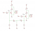
I opened this thread because within the past few days I've been designing a "breakout board" to connect a few switches to an Arduino-type microcontroller. As you can see, I have three buttons (switches A, B and C). All three buttons are momentary NO (normally open) push buttons, but I want both outputs to be NC and low active. The circuit is supplied with 12V and 5V are obtained by using a 7805 voltage regulator.
What I want the circuit to do:
Case 1:
No button is pressed. Both transistors must work within saturation region.
For both transistors, 10k pull up resistors set collector voltage to nearly 5V (GND). Additionally, base is supplied with 5V. For that transistor, VBE(sat) is 0.85V (at iB=1mA, iC=10mA). 3k9 resistors are meant to limit base current (iB) to that mentioned 1mA. Don't know if I should make 3k9 resistors a bit smaller, since 3k9 is the threshold value I got by using the formula.
Outcome for case 1:
Both outputs are "shorted" to ground, so the signal would equal GND for both cases.
Case 2:
A button is pressed. The related transistor must work within cutoff region.
For that transistor, base voltage is nearly equal to GND, so it should behave as an approx open switch.
Outcome for case 2:
The transistor in cutoff region makes the output read 5V (because the controller board has internal pull up resistor for its input pins).
How I want the switches to control the outputs:
Transistor #1 must "open" if either A or B switches (or both) are closed. If both A and B are open, transistor1 must remain closed (saturation).
Transistor #2 must "open" if either B or C switches (or both) are closed. If both B and C are open, transistor2 must remain closed.
(See Boolean attachment for clarification)
Some additional comments
1) B switch is shared between both circuits. Single mechanical switch for that, multiple signals which depend on it. That makes the whole thing a bit trickier.
2) The board has a procedure to check input pins out. No matter what the value is at other pins, no matter if other pins change. If the board is taking a step which reads output1, it sticks just to output1. That makes things way easier for me.
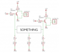
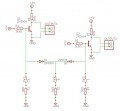
Sooo... what should I add in the blank space in order to make my circuit work as desired? I've been thinking about placing a couple of diodes (see proposed solution in attachments) facing inwards, but not really sure if that will work.
Thanks in advance for reading this, and sorry for abusing transistors on that way
I'm new to this forum. Don't know if it's common over here introducing yourself on your first post, so I'll do just in case.
INTRO
My name is Alex, and I'm (milimeters close to become) a Mech Engineer. I'm based in Madrid, Spain. I'm quite interested in 3Dprinting and manufacturing proccesses in general. My main interest among the topics shared in this forum is digital electronics, but also have tried some stuff in analog, audio operational amplifiers and similar components, but not really complex stuff. I'm not particularly happy with my university when it comes to electronics.
TOPIC ITSELF
I opened this thread because within the past few days I've been designing a "breakout board" to connect a few switches to an Arduino-type microcontroller. As you can see, I have three buttons (switches A, B and C). All three buttons are momentary NO (normally open) push buttons, but I want both outputs to be NC and low active. The circuit is supplied with 12V and 5V are obtained by using a 7805 voltage regulator.
What I want the circuit to do:
Case 1:
No button is pressed. Both transistors must work within saturation region.
For both transistors, 10k pull up resistors set collector voltage to nearly 5V (GND). Additionally, base is supplied with 5V. For that transistor, VBE(sat) is 0.85V (at iB=1mA, iC=10mA). 3k9 resistors are meant to limit base current (iB) to that mentioned 1mA. Don't know if I should make 3k9 resistors a bit smaller, since 3k9 is the threshold value I got by using the formula.
Outcome for case 1:
Both outputs are "shorted" to ground, so the signal would equal GND for both cases.
Case 2:
A button is pressed. The related transistor must work within cutoff region.
For that transistor, base voltage is nearly equal to GND, so it should behave as an approx open switch.
Outcome for case 2:
The transistor in cutoff region makes the output read 5V (because the controller board has internal pull up resistor for its input pins).
How I want the switches to control the outputs:
Transistor #1 must "open" if either A or B switches (or both) are closed. If both A and B are open, transistor1 must remain closed (saturation).
Transistor #2 must "open" if either B or C switches (or both) are closed. If both B and C are open, transistor2 must remain closed.
(See Boolean attachment for clarification)
Some additional comments
1) B switch is shared between both circuits. Single mechanical switch for that, multiple signals which depend on it. That makes the whole thing a bit trickier.
2) The board has a procedure to check input pins out. No matter what the value is at other pins, no matter if other pins change. If the board is taking a step which reads output1, it sticks just to output1. That makes things way easier for me.
Sooo... what should I add in the blank space in order to make my circuit work as desired? I've been thinking about placing a couple of diodes (see proposed solution in attachments) facing inwards, but not really sure if that will work.
Thanks in advance for reading this, and sorry for abusing transistors on that way
Attachments
-
 56.5 KB Views: 21
 -
 23.2 KB Views: 18
 -
 8.9 KB Views: 15