On-Off Momentary LED circuit for keyboard status lights?

Thread Starter

HaloArchive

Joined Nov 21, 2014
14
Hello All,

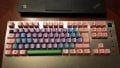
I have soldering skills but not so much on the design side. I am looking to make a circuit that has a feed of 3.3v-5v on my keyboard that when I hit the caps-lock or num-lock or scr-lock that it actuates the respective LED. The switches are mechanical so, they are momentary switches but I want to hit the switch, the led stays on until I hit the switch again.

Any cool circuits you guys have for this? -- Preferably from readily available parts on amazon or somewhere with fast (2 day) shipping.

Thanks!

EDIT: These are the LEDs that will be used: http://www.amazon.com/microtivity-I...601802&sr=8-1-spell&keywords=microivity+il188
 
Last edited:

Thread Starter

HaloArchive

Joined Nov 21, 2014
14
After looking a little, I realized I dont have a number pad so, only capslk and scrlk. I want to use a Red and a Green LED respectively.

Here is some data for the LEDs:
Forward Voltages are Red, Orange and Yellow 1.9-2.0V | Green: 2.9-3.1V | Blue, White, Pink and Violet: 3.0-3.2V.
 

MikeML

Joined Oct 2, 2009
5,444
Doesn't any normal keyboard made in the last 30years do this automatically? There are dozens of used keyboards at my local thrift store that could be bought for $1
 

RichardO

Joined May 4, 2013
2,270
I am building my own and using a beagle-bone as a controller. Pointless ... yes, cool ... yes!
If you are building your own keyboard then you will be scanning the switches with I/O lines from the microcontroller. The microcontroller will do the toggle function and LED driving using software.
 

Thread Starter

HaloArchive

Joined Nov 21, 2014
14
If you are building your own keyboard then you will be scanning the switches with I/O lines from the microcontroller. The microcontroller will do the toggle function and LED driving using software.
Unfortunately I wish to not hog clock cycles for something that can be controlled with hardware especially since I will not be using a traditional keyboard matrix. I will be doing some other things with this board as well. Regardless, I would like to build the circuit I am looking for in my original post for another project to. Could be a great learning experience :)
 

Thread Starter

HaloArchive

Joined Nov 21, 2014
14
It looks like some people use a JK-FF. Could I use a TI SN74HC109N (http://www.ti.com/lit/ds/symlink/sn74hc109.pdf) and connect the following:

Vcc to the beaglebone 3.3v
Gnd to beaglebone Gnd
1J and 1K to 3.3v
1CLR to Gnd

Button between 1CLK and Gnd
10K resistor between 1CLK and 3.3v

LED between 1Q and Gnd using whatever resistor is appropriate.

Sound right?

Thanks!
 

absf

Joined Dec 29, 2010
1,968
Even if it works with HC109, how are you going to connect the keyboard matrix to the JKFF? Does grounding one side of the keypress allowed by your keyboard circuit?

Allen
 

Thread Starter

HaloArchive

Joined Nov 21, 2014
14
Even if it works with HC109, how are you going to connect the keyboard matrix to the JKFF? Does grounding one side of the keypress allowed by your keyboard circuit?

Allen
Grounding one side shouldnt be a problem. When the key is pressed, the diode on the matrix will allow the signal through and will also allow vcc through the piggyback circuit for the light. Unless im not thinking of this correctly?
 

absf

Joined Dec 29, 2010
1,968
Grounding one side shouldnt be a problem. When the key is pressed, the diode on the matrix will allow the signal through and will also allow vcc through the piggyback circuit for the light. Unless im not thinking of this correctly?
Well, if you think so then just follow the wiring of HC109 as attached....

LED for KB status.PNG

But first try it out on a breadboard with 3.3V on Vcc. If it works as you planned, then connect the input to your keyboard matrix.

cheers...........

Allen

PS...May be you need a power-up reset on the HC109, if the LED isn't on OFF state every time you switch on your keyboard.
Try it out first and let me know.
 

Thread Starter

HaloArchive

Joined Nov 21, 2014
14
Thank you very much Allan,

Quick couple questions ... I see this chip is a dual JKFF, would it be possible to use this one chip and connect both of the FF's to control both of the lights with a different resistor for the green LED? Or, is the power rating on the spec sheet only appropriate for the total combined power output thus only allowing me to drive one led per chip?

----------
And for the second question, is there a way to use a couple of these chips to make a rotating led setup like a shift register also using a momentary button? Example:

initial state: LED 1: On, LED 2: Off, LED 3: Off
press button once: LED 1: Off, LED 2: On, LED 3: Off
press button again: LED 1: Off, LED 2: Off, LED 3: On

Thanks!
 

absf

Joined Dec 29, 2010
1,968
Quick couple questions ... I see this chip is a dual JKFF, would it be possible to use this one chip and connect both of the FF's to control both of the lights with a different resistor for the green LED? Or, is the power rating on the spec sheet only appropriate for the total combined power output thus only allowing me to drive one led per chip?
Sure, you can do that.


And for the second question, is there a way to use a couple of these chips to make a rotating led setup like a shift register also using a momentary button? Example:

initial state: LED 1: On, LED 2: Off, LED 3: Off
press button once: LED 1: Off, LED 2: On, LED 3: Off
press button again: LED 1: Off, LED 2: Off, LED 3: On
That should be easier with a 4017 chip. I tried with your JKFF and I came out with the pattern:

initial state: LED 1: On, LED 2: Off, LED 3: Off
press button once: LED 1: on, LED 2: On, LED 3: Off
press button again: LED 1: on, LED 2: on, LED 3: On

Di you try google "making a shift register using JK flip flop"

That should give you some clue...........

Allen
 

djsfantasi

Joined Apr 11, 2010
9,155
Or use a shift register… 74HC595, although supporting circuitry necessary may make it undesirable.

I do like the 4017 chip.

I'd say, don't get hung up on the JKFF. Remember the old saying, if all you have is a hammer then everything starts to look like a nail.
 

Thread Starter

HaloArchive

Joined Nov 21, 2014
14
Well, Id prefer to use a bunch of 74HC109's because that is what I have on hand and dont really want to wait several days for another chip :)

Sure, you can do that.

That should be easier with a 4017 chip. I tried with your JKFF and I came out with the pattern:

initial state: LED 1: On, LED 2: Off, LED 3: Off
press button once: LED 1: on, LED 2: On, LED 3: Off
press button again: LED 1: on, LED 2: on, LED 3: On

Di you try google "making a shift register using JK flip flop"

That should give you some clue...........

Allen
Allen,

That would work as well ... Lets say I used the LEDs with the 3.0v forward voltage, do you have a schematic for it?

After the third press, does it go back to the initial state or an all-off state?

And yes, I did initially convert the JKff's into Dff's from my college days and tried to make a shift register but I think I had things wired incorrectly.


Or use a shift register… 74HC595, although supporting circuitry necessary may make it undesirable.

I do like the 4017 chip.

I'd say, don't get hung up on the JKFF. Remember the old saying, if all you have is a hammer then everything starts to look like a nail.
Im at the point everything is a nail :) But yes, in the future when I run low on JKff's I may decide to widen my spectrum of available logic chips.

... as of right now I have 20 dual jkff's 74HC109
 

absf

Joined Dec 29, 2010
1,968
OK, here's the led chaser using your JKFF HC109. It needs a 555 timer for the clock and an extra 74HC04 NOT gates. If you dont have HC04 you may use NPN transistors and resistors wired as inverters.

See attached HC109 led chaser.PNG

The LED chaser would have the pattern mentioned above and all LED would be Off when it reaches the n-1 LED. The nth output is used to reset the JKFF and cannot be used to light up a LED. You can cascade as many JKFF as you want provided your DC supply is sufficient to provide the current needed. For example using 6 JKFF would give you 6n-1 ie (6x2)-1 or 11 LEDs.

Hope you have a 555 in your spare box.

Allen

[update] R5 may not be needed. you can remove it.
 

Thread Starter

HaloArchive

Joined Nov 21, 2014
14
OK, here's the led chaser using your JKFF HC109. It needs a 555 timer for the clock and an extra 74HC04 NOT gates. If you dont have HC04 you may use NPN transistors and resistors wired as inverters.

See attached View attachment 76187

The LED chaser would have the pattern mentioned above and all LED would be Off when it reaches the n-1 LED. The nth output is used to reset the JKFF and cannot be used to light up a LED. You can cascade as many JKFF as you want provided your DC supply is sufficient to provide the current needed. For example using 6 JKFF would give you 6n-1 ie (6x2)-1 or 11 LEDs.

Hope you have a 555 in your spare box.

Allen

[update] R5 may not be needed. you can remove it.
Excellent, I will build inverters with a 2N3904 and two 1k resistors. Seems it should work. I will breadboard this tomorrow and report back.

Thanks so much!

EDIT:

Just realised the 555 was for driving the chaser. However, it will also be operated off of a momentary pushbutton. I will just place the pushbutton similar to the first schematic.
 

Thread Starter

HaloArchive

Joined Nov 21, 2014
14
Alright, update post ... It looks like I need to debounce the switch ... only works sometimes. What would I add onto the schematics?
 

djsfantasi

Joined Apr 11, 2010
9,155
Here is a good reference to debouncing switches. You can use a simple RC circuit to debounce your input (few parts). I was looking for the specs on your input voltage, but didn't see them. If they're in the range of CMOS logic gates, you can use an SR latch as a debouncer.

The RC circuit is as follows. Note in this example, the switch is connected to ground. Later, is an example where the switch is connected to Vcc.


And here is an example of how it is used connected to a JKFF. Note in this example, the switch is connected to Vcc.
 

absf

Joined Dec 29, 2010
1,968
Since you dont have 4027 JKFF, you may use HC109 as the debouncer as in the circuit above.

I think it is time to get some more chips like 555, 4017, inverters, NAND and NOR gates if you want to progress with your experiments.

BTW, is the circuit in post #11 working? Did you try it out on your keyboard?

Allen
 
Top