 Facebook
 Google
 GitHub
 Linkedin
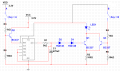
Are you sure ?? How large will be this base current ?? Are you suggesting that the LED will burn?I think I have the answer. As the emitter of the transistor is raised from zero to 1.5 volts, the voltage from collector to emitter becomes less. If you're using a blue or white LED, that is going to eat up about 3.2V to 3.4 V. What's left for the transistor? About 0.2 volts collector to emitter. That puts the transistor in the range where its DC gain approaches zero. Then it becomes a (base) current hog, like takao said.
For this circuit
http://forum.allaboutcircuits.com/attachments/5v-fader-png.77472/
Base current cannot be larger than
Ib_max = (Vcc - 2Vd - Vbe )/Re = 32mA But what about the LED current?


")


