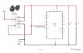
Thank you for the additional suggestions. I've updated the drawing to reflect the new switch wiring suggestion, and added caps on the right side. What sort of values would be good for "fat caps" C1 and C2?
I'm wondering if it would still be a good idea to have a small value resistor in the line that connects to input pin A3? Just wouldn't want to burn out the pin, but I might be concerned over nothing here.
Well, haw fat do you want the caps? The value depends on two things: A-how much current the Arduino draws, and 2) how much it supplies to the rest of the circuit.
A cap will droop (in volts) I * T / C, where I is in amps, T is in seconds, and C is in Farads, so if your circuit draws 50mA total and you want no more then 1V of droop in 1/10 a second your cap needs be: C = I * T / V = .05 * 0.1 / 1.0 = .005 F or 5,000 uF.
That's a pretty fat cap!
I would not use a resistor to protect the pin as everything is self contained.
BUT... one day, maybe not for a year or two, but one day, this circuit will fail. Why? Because you are using a power switch for a logic signal, and power switches need some current to "burn" the contacts clean, least they oxidize over time. I'd use at least 1mA (R=5K) to form the switch, and 10 or 20mA if I could "afford" it (meaning it isn't battery power).
Here's one way to get that current, put a resistor back:
ErnieM, thanks for this. I like it, and have made another version of my drawing.
There is a 470 ohm resistor in place for now (it would give 10.6mA), but will adjust if needed. 5V comes from a plugged in power supply so that will be fine. And thank you for the capacitor calculation breakdown. Fat cap! I will look into this.
Also, to make the drawing a bit cleaner I swapped sides where the wires connect on the lower part of switch.
 Facebook
 Google
 GitHub
 Linkedin

 Thanks


