Old School Clock - How to get it to work without a Master? (2)

Thread Starter

TERKYKE

Joined Jul 3, 2025
1
This type of clock often works by receiving a low current impulse at a fixed interval - typically once every 30 seconds. This site: http://www.hvtesla.com/masters/index.html illustrates typical examples of master/slave clock arrangements.
By wiring the slave clocks in series, it is possible to drive any number of slaves from one master clock impulse generator.

Although they were usually electronmechanical in operation, you can recreate a 'master clock' using an electronic crystal oscillator and divider, driving an external relay or solid state current sink devices, which is designed to provide a (typical) 200mA pulse every 30 seconds.

I fitted one to an old bowling club clock 'slave', a while back. (Video of the installation here:
if you're interested)

If that's the kind of thing you're looking at, I'll try and find the circuit if it's likely to be of any use?
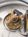
I’m looking to buy five clocks off of eBay, but they’re on a slave system. Are these clocks able to run independently by themselves without a master clock, correcting the time?

Moderator edit: New thread created from this.
 

MisterBill2

Joined Jan 23, 2018
27,319
There are several different schemes for those clocks, and most of them require that master control device, which you will not be able to get, nor easily duplicate. The series string clocks are the antiques, the newer ones will be triggered by a signal impressed on the mains power. That signal may be around 1000Hertz, or a bit higher. AND some of the systems use that sort of signal to run the clock for setting.
So there are quite a few different schemes and if you do not have the details your choice is to replace the drive with either a currently available battery movement or a mains powered movement.
 

MisterBill2

Joined Jan 23, 2018
27,319
I have a few old 24 Volt slave clocks that I got running with a diver circuit.
It uses an MCU and a 32.768 Khz crystal to keep time, it boosts the 3V battery voltage (2 X D-cells) to 24 volts to fire the coil once a minute.

View attachment 352206View attachment 352207
Very Good!! It is obvious that you are not a beginner! The design is great in it's simplicity. The complex part is in the PIC device coding.
 

MisterBill2

Joined Jan 23, 2018
27,319
There are several very different systems for operating clocks in unison, and so without having any hint as to which scheme the unknown clocks use, any advice will be a random guess.
 

marcf

Joined Dec 29, 2014
299
Back in the day, I maintained clocks like this. The units I maintained had 2 solenoids. One solenoid advanced the time 1 min, the other solenoid set the hour hand. (Next hour if time was less than 30 mins to the next hour, previous hour if time was less than 30 mins from the previous hour). If both solenoids were activated the clock reset to 6:30. These were, beleive Standard Time clocks. The oldest one I worked on was installed in 1924.
The clocks were controlled from one master controller and the network was for a large campus (> 1 sq mile.) and each building had a repeater unit slaved to the master.
I have been retired for some time and have forgotten a lot of the gory details. If anyone has more info on these I would like to see it.
 

MisterBill2

Joined Jan 23, 2018
27,319
Back in 1967 I acquired a box of the clock signal controller modules that were removed during a clock system upgrade. They had two tuned circuits, loosely coupled, with the series circuit being across the 120 volt mains and the parallel circuit driving the "grid" of a cold cathode thyratron tube. Those circuits were tuned to between 1200 and 1500 Hz. So that control scheme was a bit different. The trigger signal was generated by a motor/generator system that used a 1/2 HP synchronous motor that ran constantly. I had seen smaller building clock systems where the tone signal transmitter used four 6L6 tubes as the output stage.
 
Top